1.Overview
TheY-703N ATS controller is used in conjunction with a dual power transfer switch (TSE) to form an automatic transfer switch(ATSE)It detects abnormal conditions of grid parameters(overvoltage,undervoltage,phase loss,over frequency,under frequency,misphase sequence,etc.)and then control the transfer switch(TSE) transfer according to a predetermined mode of operation to the suitable power supply,to ensure the continuous power supply on the load side.
2.Features
1).Microcontroller-based measurement and control system with true RMS calculation for the basic parameters of the power grid;
2).Adjustable transfer delay and operation modes for various applications;
3).The combination of Chinese and English LCD dot matrix screen and LEDs providesclear and accurate information;
4).Equipped with programmable relay output contact,active and passive fire signal interface,optional communication interface;
5).Can check 10 fault records;
6).Protection level:IP50.
3.Operating Environment
3.1 The ambient air temperature should range between -20°C and +70°C;
3.2 Installation site:The altitude should be the same as TSE;
3.3 Pollution level:Level 3.With no explosive hazards,corrosive gases,liquids,or conductive dust that may damage metal components or insulation in the surrounding air;
3.4 Atmospheric conditions:The ambient air temperature should not exceed +40°C,with an average temperature within 24 hours not,When the maximum temperature is +40°C,the relative humidity should not exceed 50%.Higher humidity is permissible at lower temperatures(e.g.,up to 90%at+20℃).Special measures should be taken for occasional condensation due to temperature changes;
3.5 If these conditions above are not met,please consult our company for further solutions.
4.Controller Specification
| Working power supply |
Powered by Phase A of Power Supply I/II,voltage range:AC 80~320V,50/60Hz |
| Operation mode of TSE |
Automatically transfer and restore(optional:Power l priority or Power ll priority)
Mutual backup(Automatically transfer and nonautomatically restore) |
| Real-time display of power grid parameters |
Display the phase voltage and frequency of Power l and Power ll |
| Voltage measurement method |
Three-phase four-wire system,phase voltage measurement |
| Range and accuracy of voltage measurement |
Range:60~350V,accuracy:±1%of reading+1 digit @25℃,±3%+1 digit @(-20~70)℃ |
| Rated frequency |
50Hz、60Hz |
| Voltage detection function |
Phase loss detection,overvoltage/undervoltage detection |
| Phase sequence detection |
By default,it is set to alarm. |
| Frequency detection function |
Frequency fault alarm:±2Hz deviation from rated frequency.By default,it is set to alarm. |
| Passive fire input |
Connect to external passive switch or contact |
| Active fire input |
Connect to external DC9-36V active signal |
| The transfer delay is adjustable |
Setting range:0-99.9s |
| Overvoltage and undervoltage is adjustable |
Undervoltage:70~100%;Overvoltage:100%~130% |
| Start generator function |
Relay contact output(programmable relay) |
| Generator start and stop time |
Setting range:0-999s |
| Programmable relay |
Relay contact output,3A/250V resistance |
| Communication function(optional) |
RS485 isolation interface,Modbus RTU protocol |
| Recording function |
It can record 10 faults of the voltages of each phase |
 PC ATS YECT1-2000G
 PC ATS YES2-63~250GN1
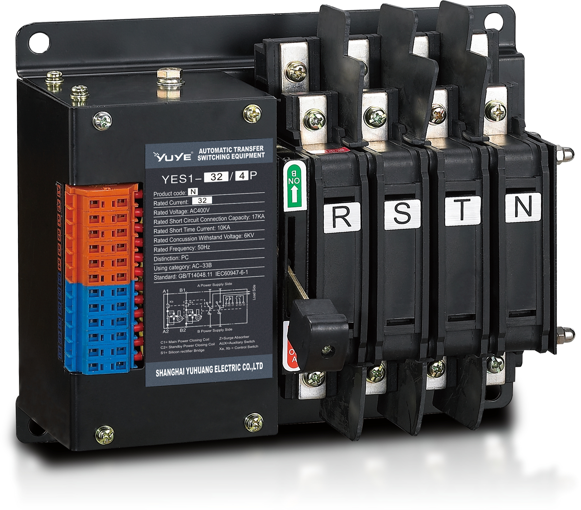 Solenoid-type ATS YES1-32~125N
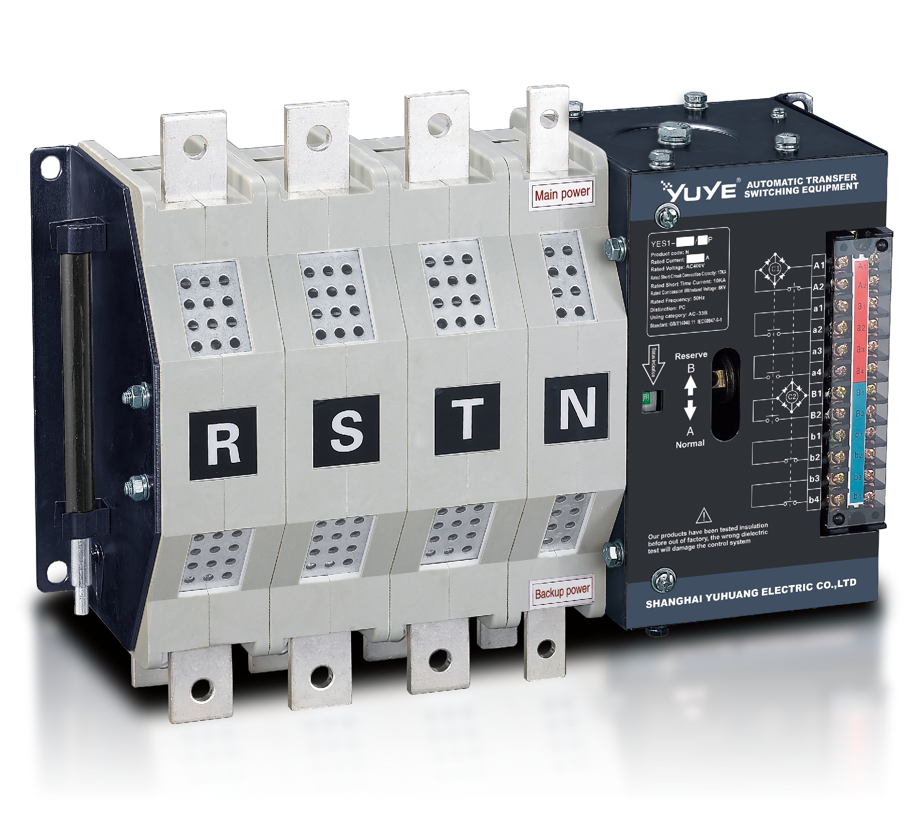 Solenoid-type ATS YES1-250~630N/NT
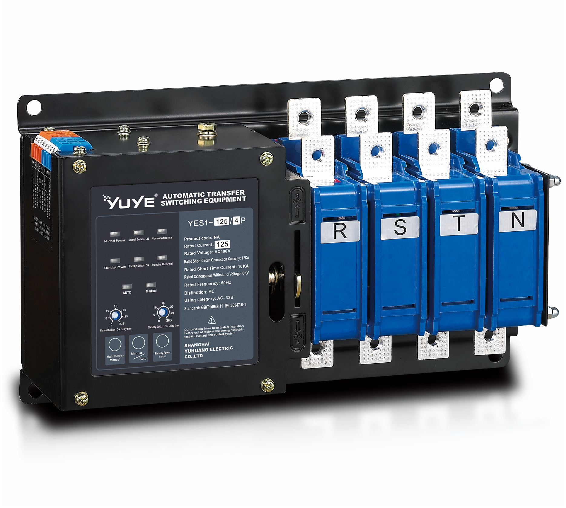 Solenoid-type ATS YES1-32~125NA
 Solenoid-type ATS YES1-63~630SN
 Solenoid-type ATS YES1-1250~4000SN
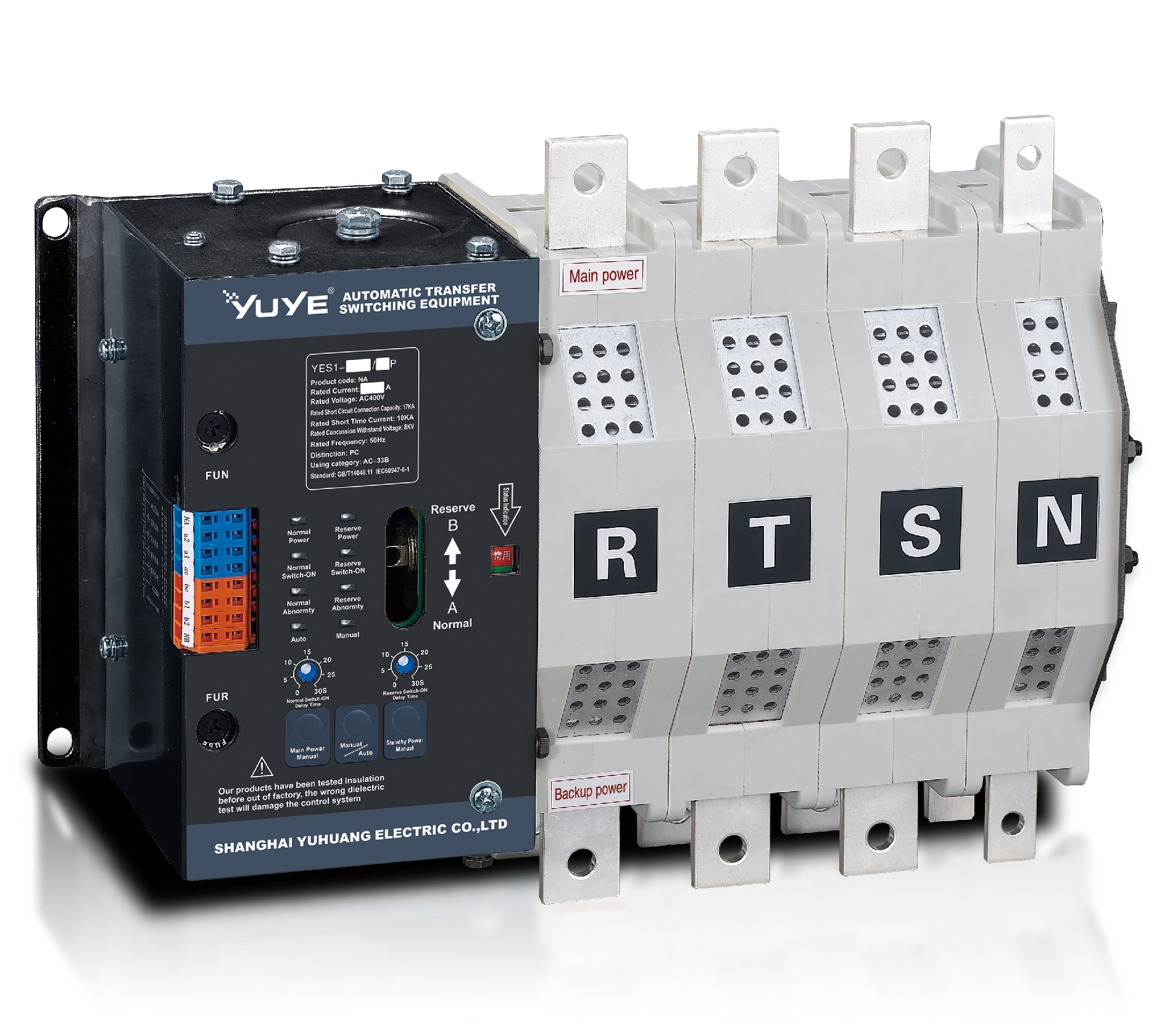 Solenoid-type ATS YES1-250~630NA/NAT
 Solenoid-type ATS YES1-63NJT
 PC ATS YES1-100~1600GN1/GN/GNF
 PC ATS YES1-2000~3200GN/GNF
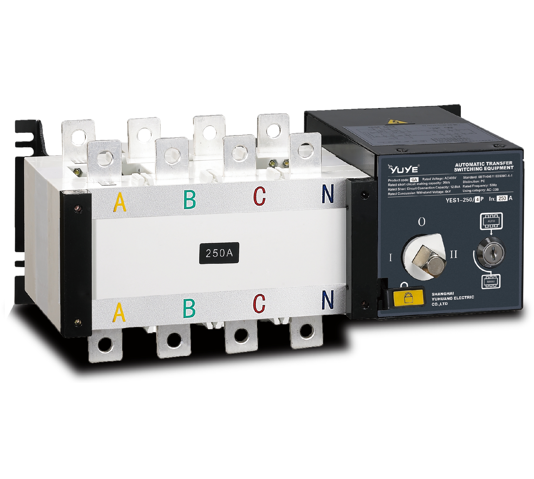 PC ATS YES1-100~3200GA1/GA
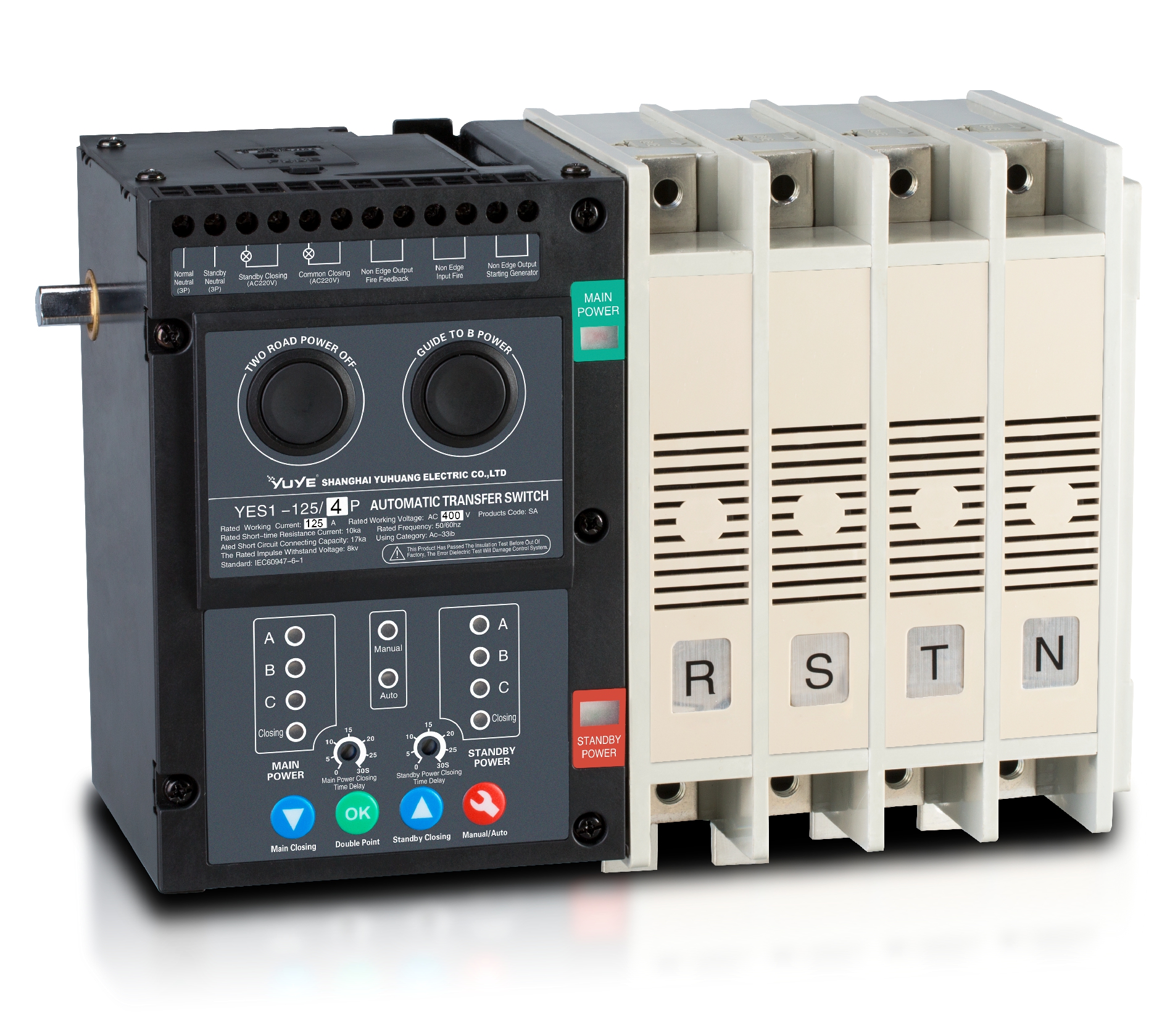 Solenoid-type ATS YES1-63~630SA
 Solenoid-type ATS YES1-63~630L/LA
 Solenoid-type ATS YES1-63~630LA3
 Solenoid-type ATS YES1-63MA
 PC ATS YES1-630~1600M
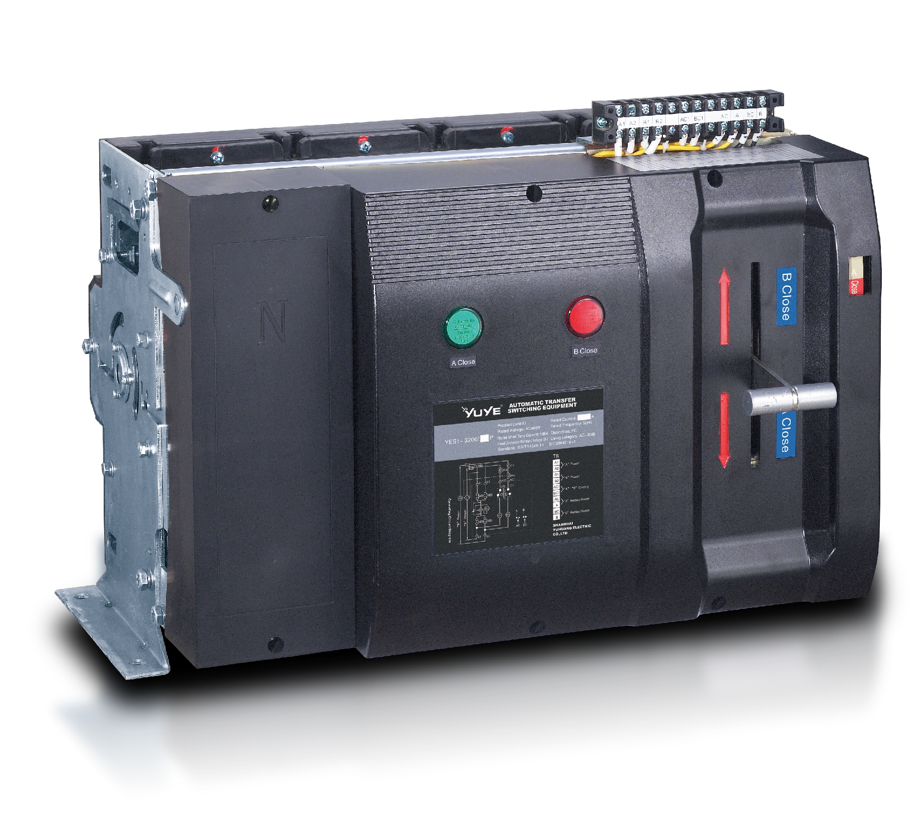 PC ATS YES1-3200Q
 Solenoid-type ATS YES1-4000~6300Q
 CB ATS YEQ1-63J
 CB ATS YEQ2Y-63
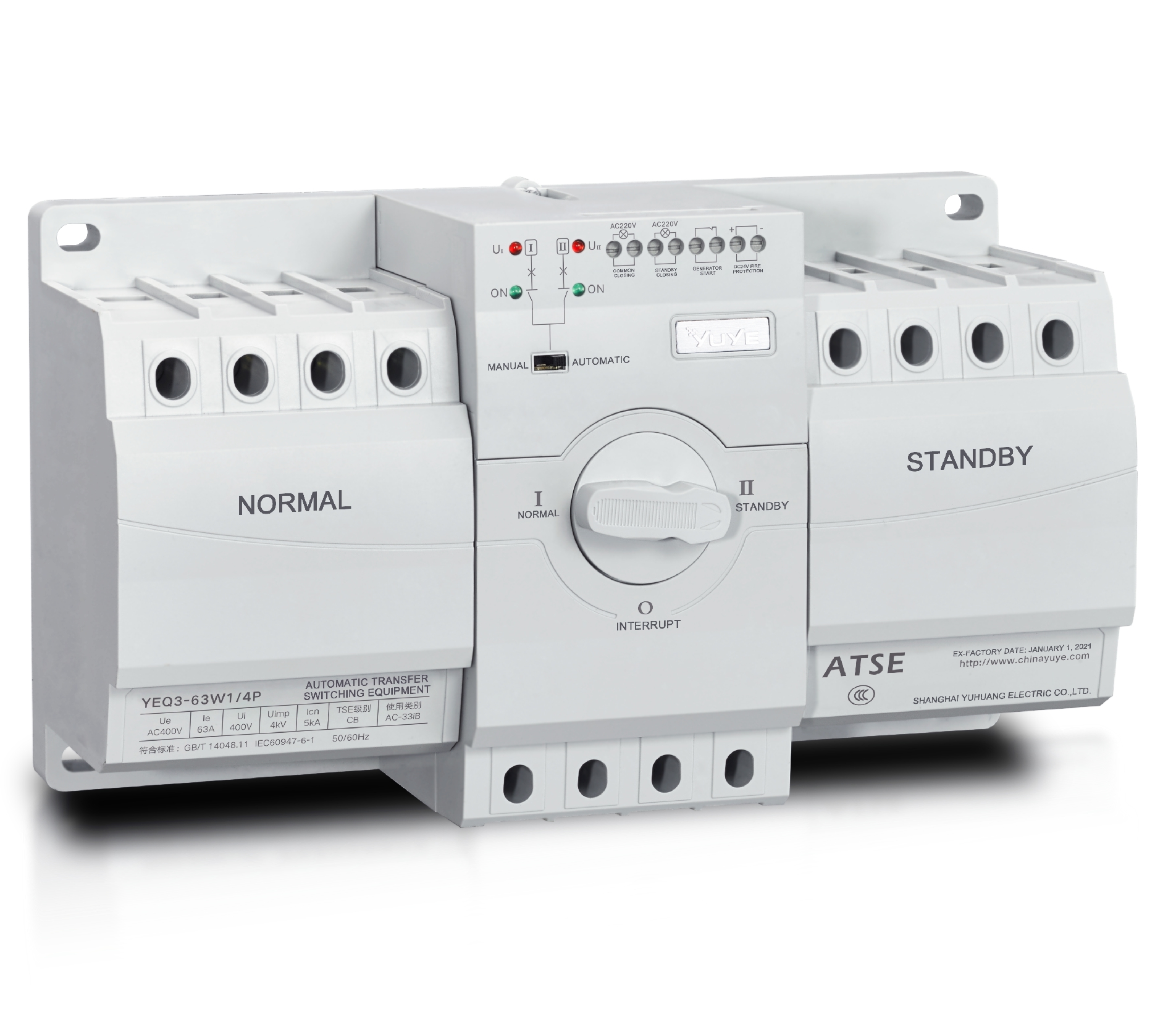 CB ATS YEQ3-63W1
 CB ATS YEQ3-125~630W1
 ATS controller Y-700
 ATS Controller Y-700N
 ATS Controller Y-701B
 ATS Controller Y-703N
 ATS Controller Y-800
 ATS Controller W2/W3 Series
 ATS switch Cabinet floor-to-ceiling
 ATS switch cabinet
 JXF-225A power Cbinet
 JXF-800A power Cbinet
 YEM3-125~800 Plastic Shell Type MCCB
 YEM3L-125~630 Leakage Type MCCB
 YEM3Z-125~800 Adjustable Type MCCB
 YEM1-63~1250 Plastic Shell Type MCCB
 YEM1E-100~800 Electronic Type MCCB
 YEM1L-100~630 Leakage Type MCCB
 Miniature circuit breaker YEMA2-6~100
 Miniature circuit breaker YEB1-3~63
 Miniature circuit breaker YEB1LE-3~63
 Miniature circuit breaker YEPN-3~32
 Miniature circuit breaker YEPNLE-3~32
 Miniature circuit breaker YENC-63~125
 Air Circuit Breaker YEW1-2000~6300
 Air Circuit Breaker YEW3-1600
 Load isolation switch YGL-63~3150
 Load Isolation Switch YGL2-63~3150
 Manual Changeover Switch YGL-100~630Z1A
 Manual Changeover Switch YGLZ1-100~3150
 YECPS2-45~125 LCD
 YECPS-45~125 Digital
 CNC Milling/Turning-OEM
 DC relay MDC-300M
 DC Isolation Switch YEGL3D-630


