1.Overview
This series of double power automatic transfer switch is suitable for automatic transfer between two power sources in emergency power supply system with rated working voltage of 400V and below,rated frequency of 50Hz and rated current of 16A to 3200A,to ensure continuous,safe and reliable operation of important loads(such as fire fightingload).It is widely used in hospitals,shopping malls,banks,chemical industry,high-risebuildings,military facilities,fire protection and other important places where power cuts are not allowed.
This product conforms to GB/T 14048.11-2016 Low-voltage switchgear and controlgear-part 6-1:multi-functional electrical switch appliances-switching device,conforms to "GB50045-1995 high-rise civil building fire code",2005 revision,"GB 5006-2014 Code for Fire Protection in Building Design","GB 51309-2018 Standard for Fire Emergency Lighting and Evacuation Indication System","GB 17945-2010 Fire Emergency Lighting and Evacuation Indication System","GB51348-2019 Electrical Design Standards for Civil Buildings,etc.
2.Performance and characteristics
□ With overvoltage,undervoltage and open phase switching function.
□ The main loop adopts double breakpoint horizontal pull structure,connected and broken reliably;
□ In line with the requirements of the isolation switch standard,with clear on-off position indication and padlock,reliable isolation function;
□ There is a disconnect position(disconnect the common and standby power supply at the same time),to meet the requirements of fire linkage;
□ Four operating functions:emergency manual operation,electric remote control operation,automatic control state emergency disconnect operation Automatic control operation.
3.Normal working conditions
□The operating ambient temperature ranges from-5℃~+40℃,and the average temperature within 24 hours does not exceed+35℃.The ambient temperature ranges from-25℃~+55°℃,and can reach+70℃ in a short time(within 24 hours).
□The elevation of the installation site shall not exceed 2000m.
□The relative humidity of the air at the installation site should not exceed 50% when the ambient airtemperature is +40℃.The relative humidity can be higher at a lower temperature.For example,when the average minimum temperature of the wet test month is+20℃,the average maximum relative humidity of that month can reach 90%.Appropriate measures should be taken to prevent condensation caused by temperature change.
□Pollution Class 3(there is conductive pollution,orthe dry non-conductive pollution becomes conductive due to condensation
□ATSE can be installed vertically or horizontally in the cabinet.Special orders are required for special requirements.
□Product shell protection grade is IP20
□Overvoltage class
-Main circuit Class I
-Control and auxiliary circuits ClassII.
□Conversion controller and auxiliary circuit installation class:II.
4.Product details
| Type |
YES1-GN、YES1-GNF |
| Current frame |
3200 |
| Rated working current(le) |
2000 |
2500 |
3200 |
| Rated insulation voltage(Ui) |
1000V |
| Rated impulse withstand voltage(Uimp) |
12kV |
| Rated working voltage(Ue) |
AC400V/50Hz |
| Use catagory |
AC-33iB |
| Rated limited short circuit current(Icm) |
105kA |
| Rated short-time withstand current (Icw) |
50kA/60ms |
| Transfer time |
3.7s |
5.Switch debugging description
1.The installation and debugging of the product shall be carried out by professionals and those who are familiar with the switch equipment operations.
2.The corresponding protection and preventive measures should be considered before debugging.The connection mode of the switch main loop must make the lead wire free from any pressure or strong action.
3.Before debugging,check whether the switch is not damaged or has any other harmful environmental impact,and check whether the wire head should be loose during transportation;Clean up dirt,especially on the surface of insulation.
4.When connecting the primary circuit,it should be noted that the phase sequence of the main and standby power must be consistent;when connecting the secondary control circuit,it should be operated strictly in accordance with the instructions;when the switch is installed,it must be well grounded.
5.After the product is installed,the power will be turned off.Take out the special operating handle supporting the product and turn it from the usual to the standby,and then from the standby to the three cycles in common use.
6.check the wiring and secondary loop at atime,after confirmed,the products are in acommon location,were used and the standby power supply,and then disconnectcommon power supply,the product after a delay the transformation to the standby power,restore common power supply,then after time delay shall be returned to the common power supply(except since couldn't from complex),three loop operation and each timeinterval of more than 20s.
 PC ATS YECT1-2000G
 PC ATS YES2-63~250GN1
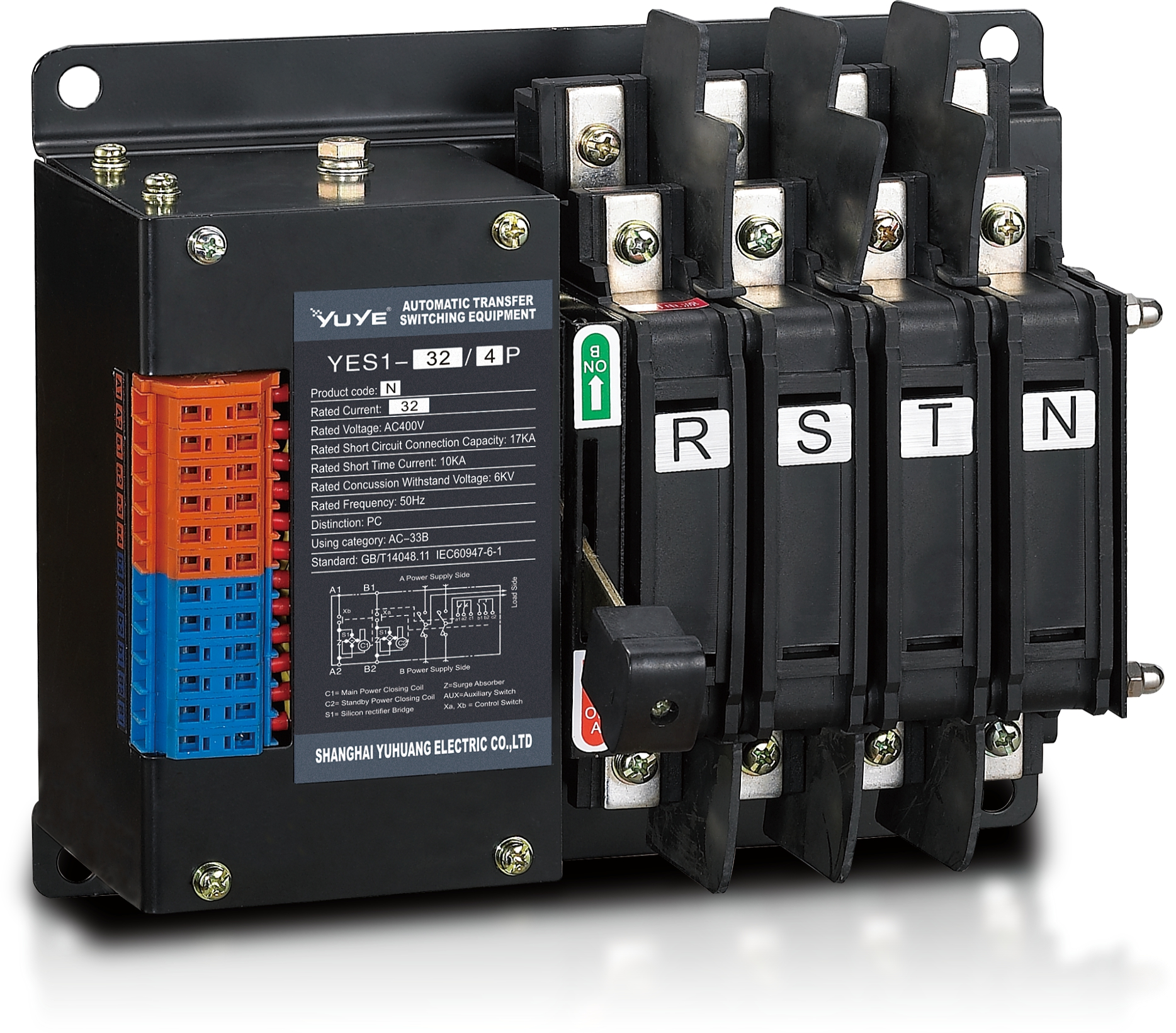 Solenoid-type ATS YES1-32~125N
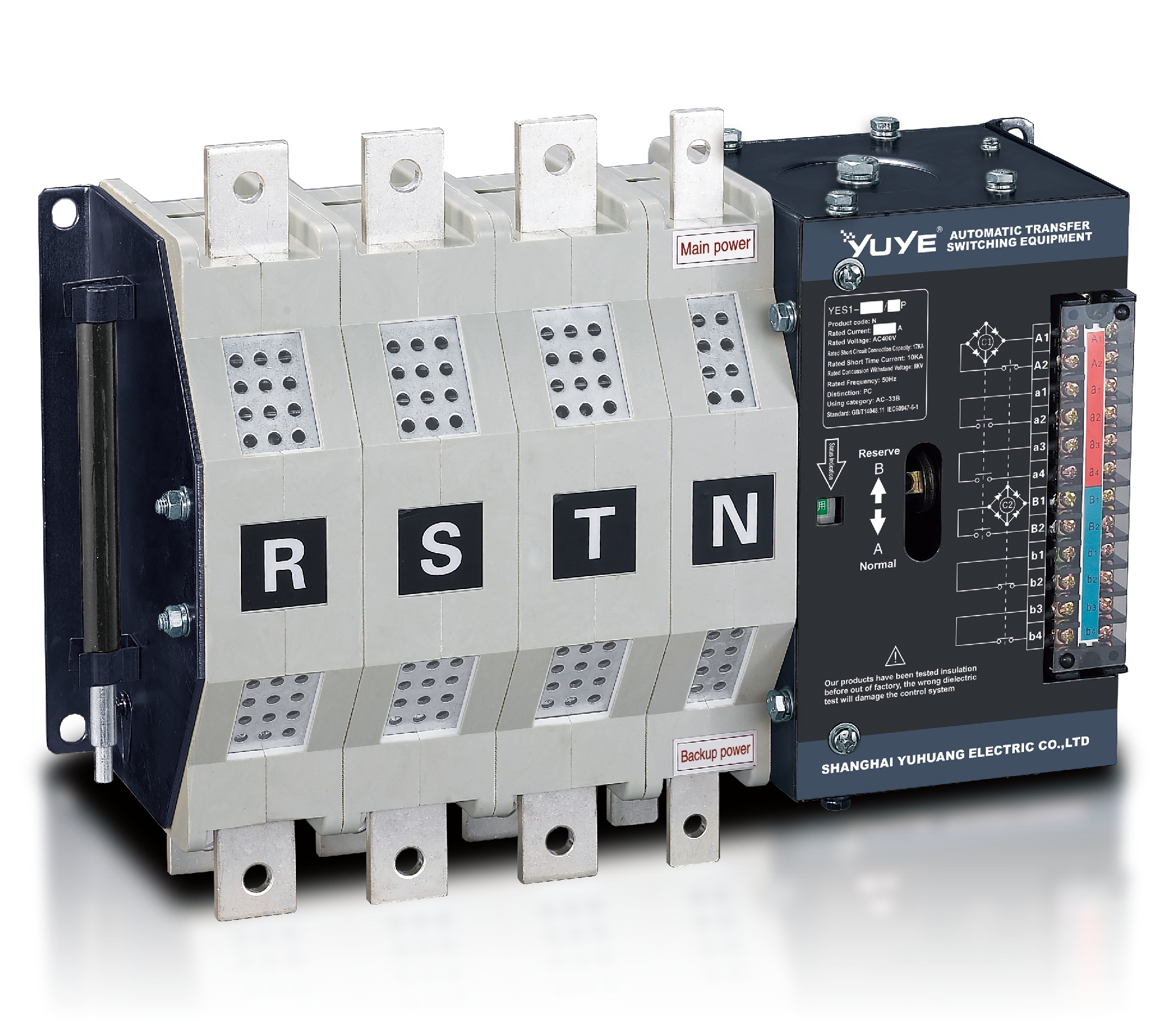 Solenoid-type ATS YES1-250~630N/NT
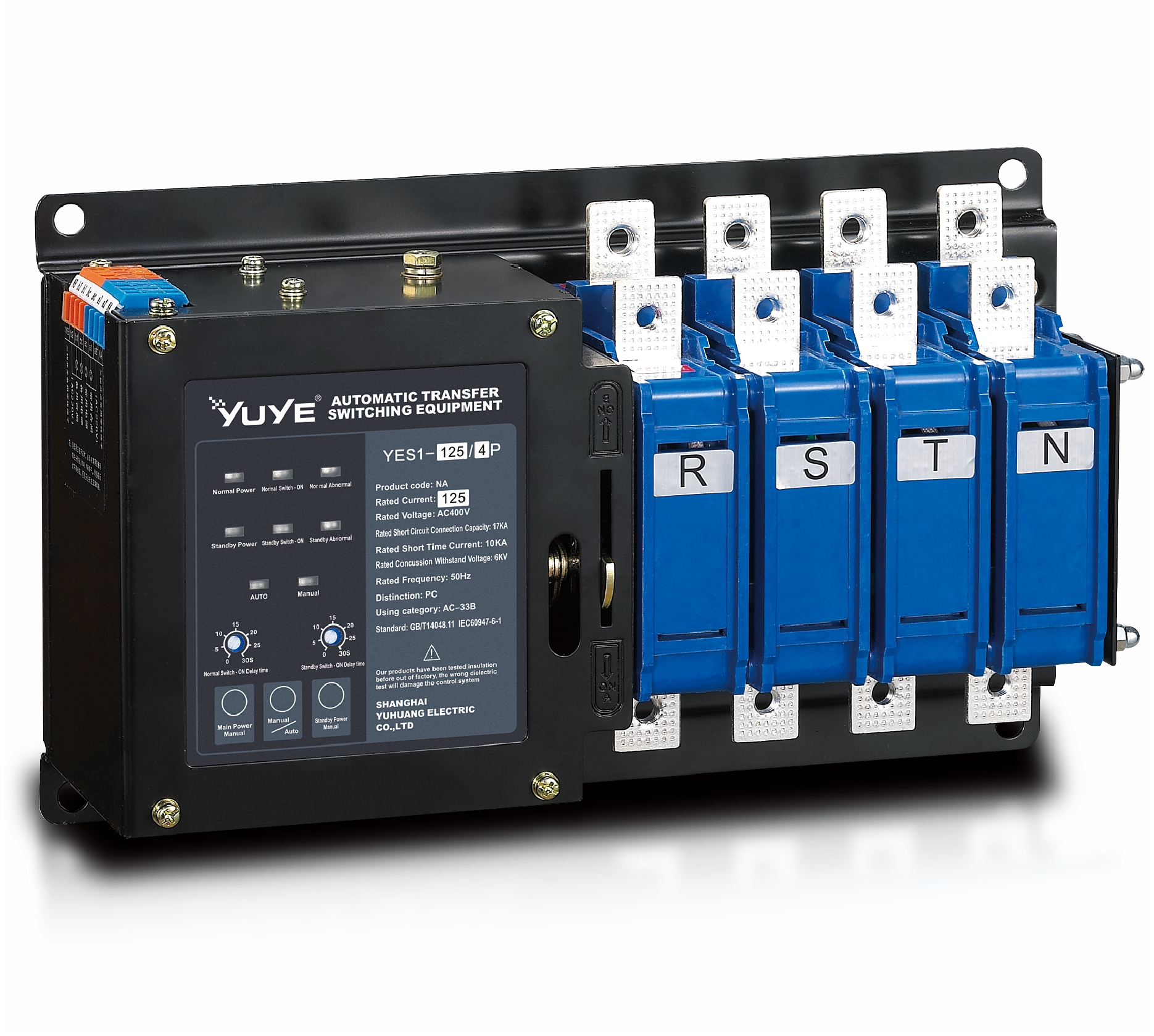 Solenoid-type ATS YES1-32~125NA
 Solenoid-type ATS YES1-63~630SN
 Solenoid-type ATS YES1-1250~4000SN
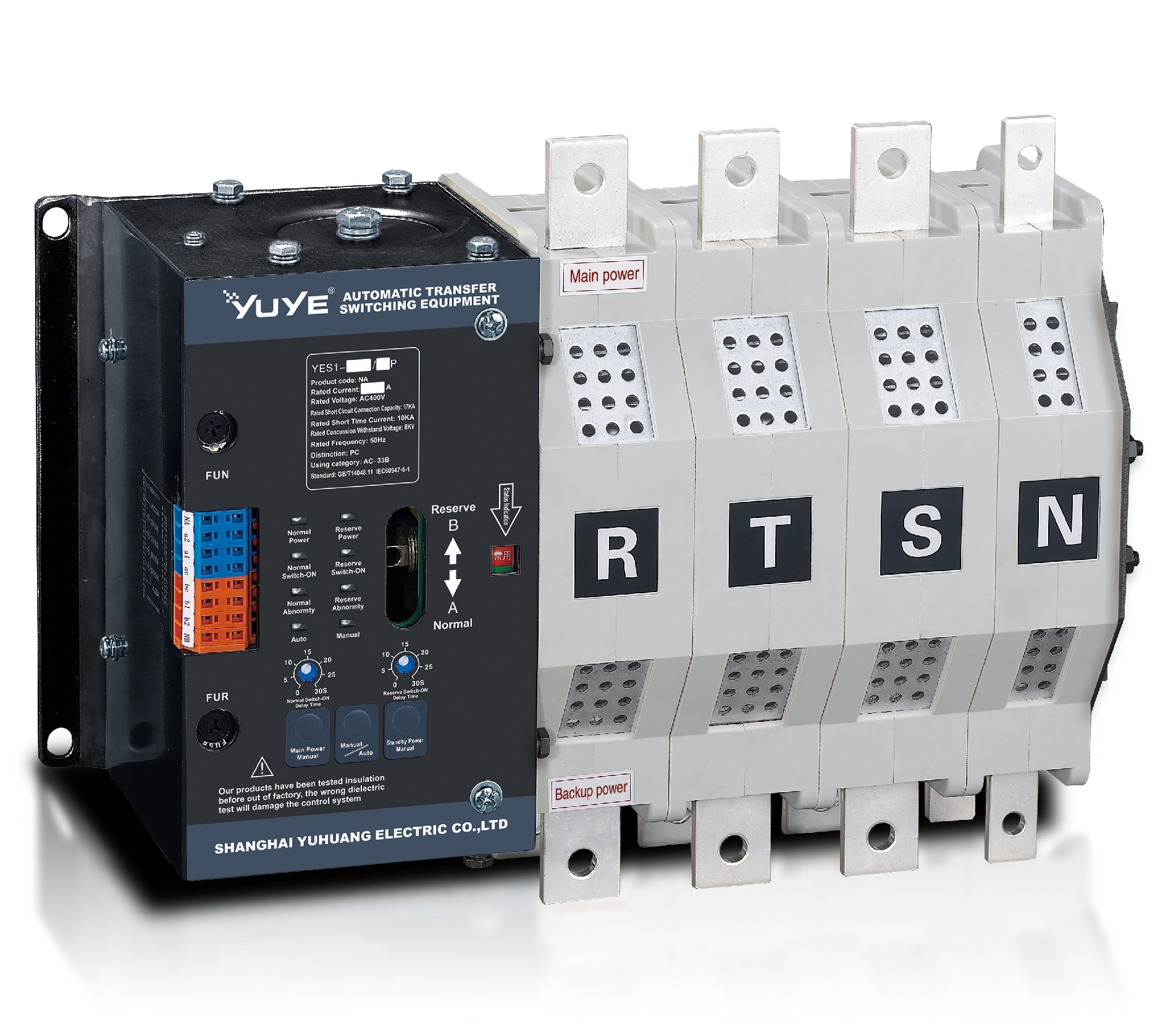 Solenoid-type ATS YES1-250~630NA/NAT
 Solenoid-type ATS YES1-63NJT
 PC ATS YES1-100~1600GN1/GN/GNF
 PC ATS YES1-2000~3200GN/GNF
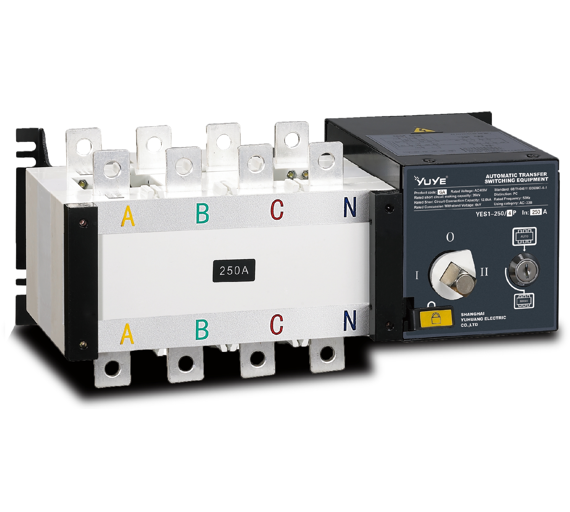 PC ATS YES1-100~3200GA1/GA
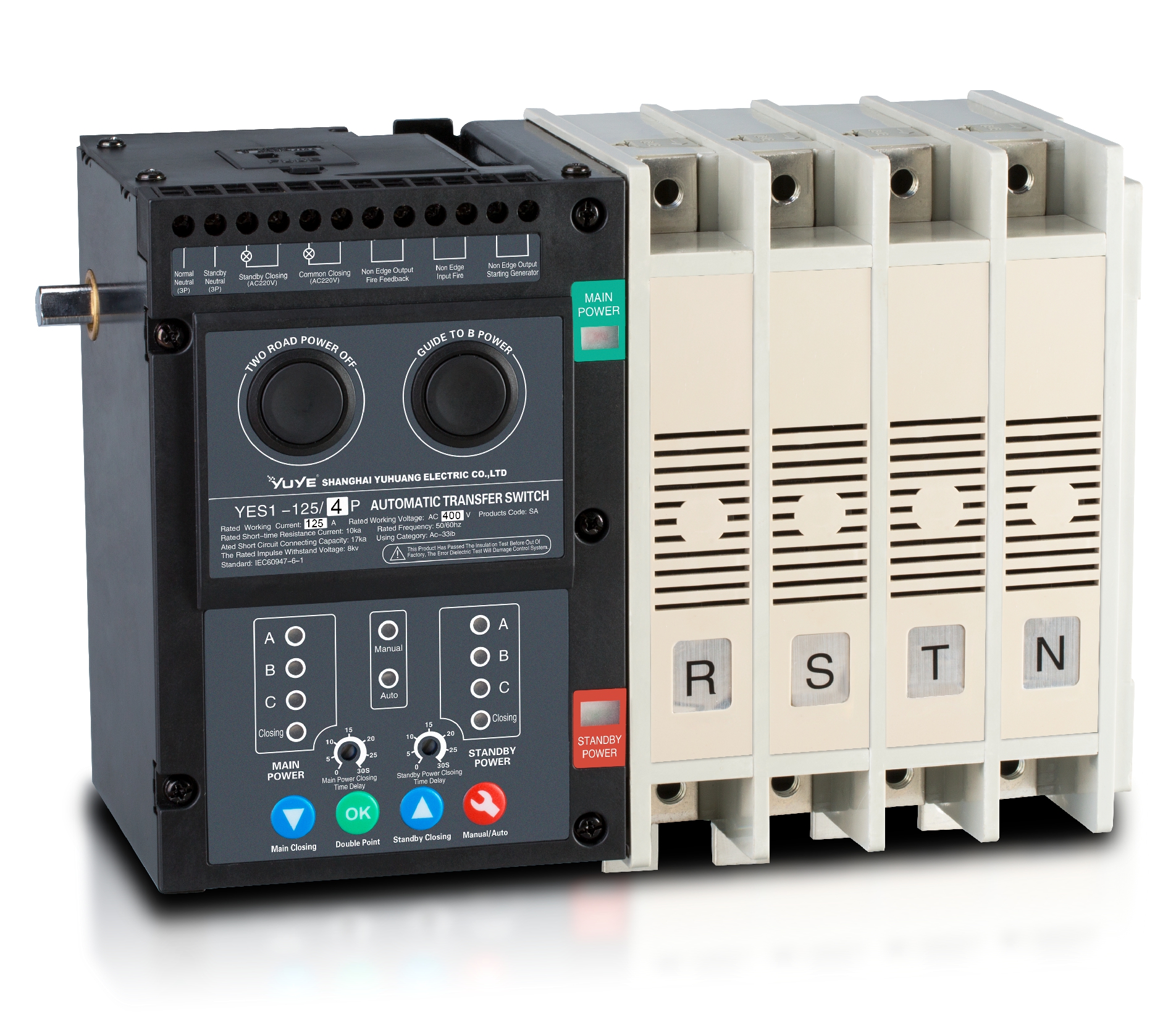 Solenoid-type ATS YES1-63~630SA
 Solenoid-type ATS YES1-63~630L/LA
 Solenoid-type ATS YES1-63~630LA3
 Solenoid-type ATS YES1-63MA
 PC ATS YES1-630~1600M
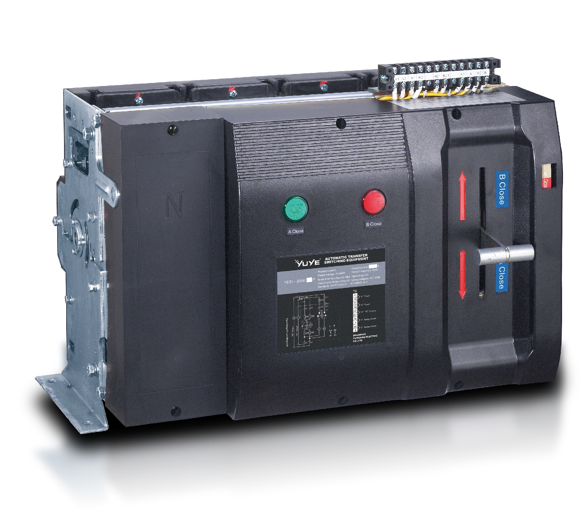 PC ATS YES1-3200Q
 Solenoid-type ATS YES1-4000~6300Q
 CB ATS YEQ1-63J
 CB ATS YEQ2Y-63
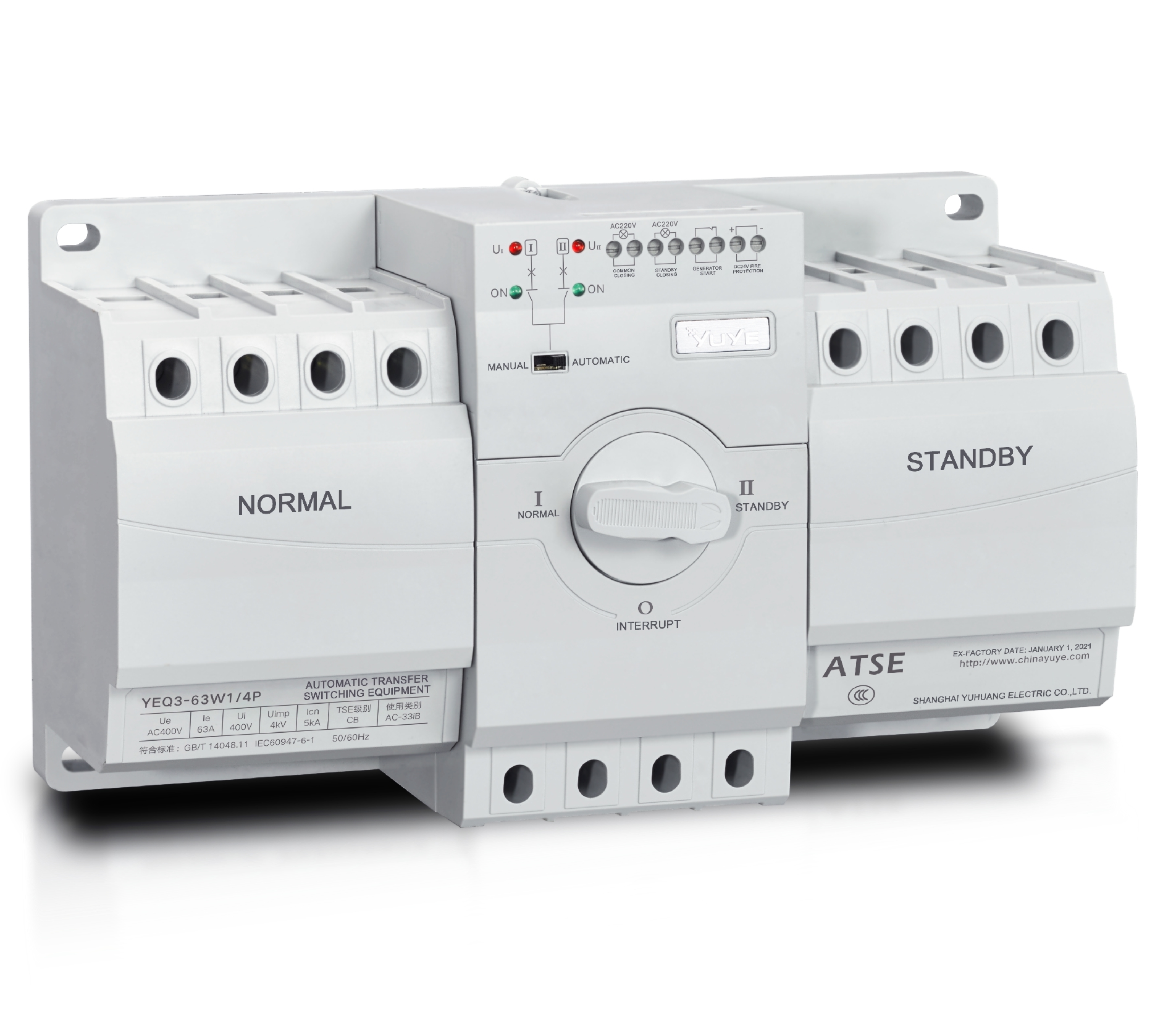 CB ATS YEQ3-63W1
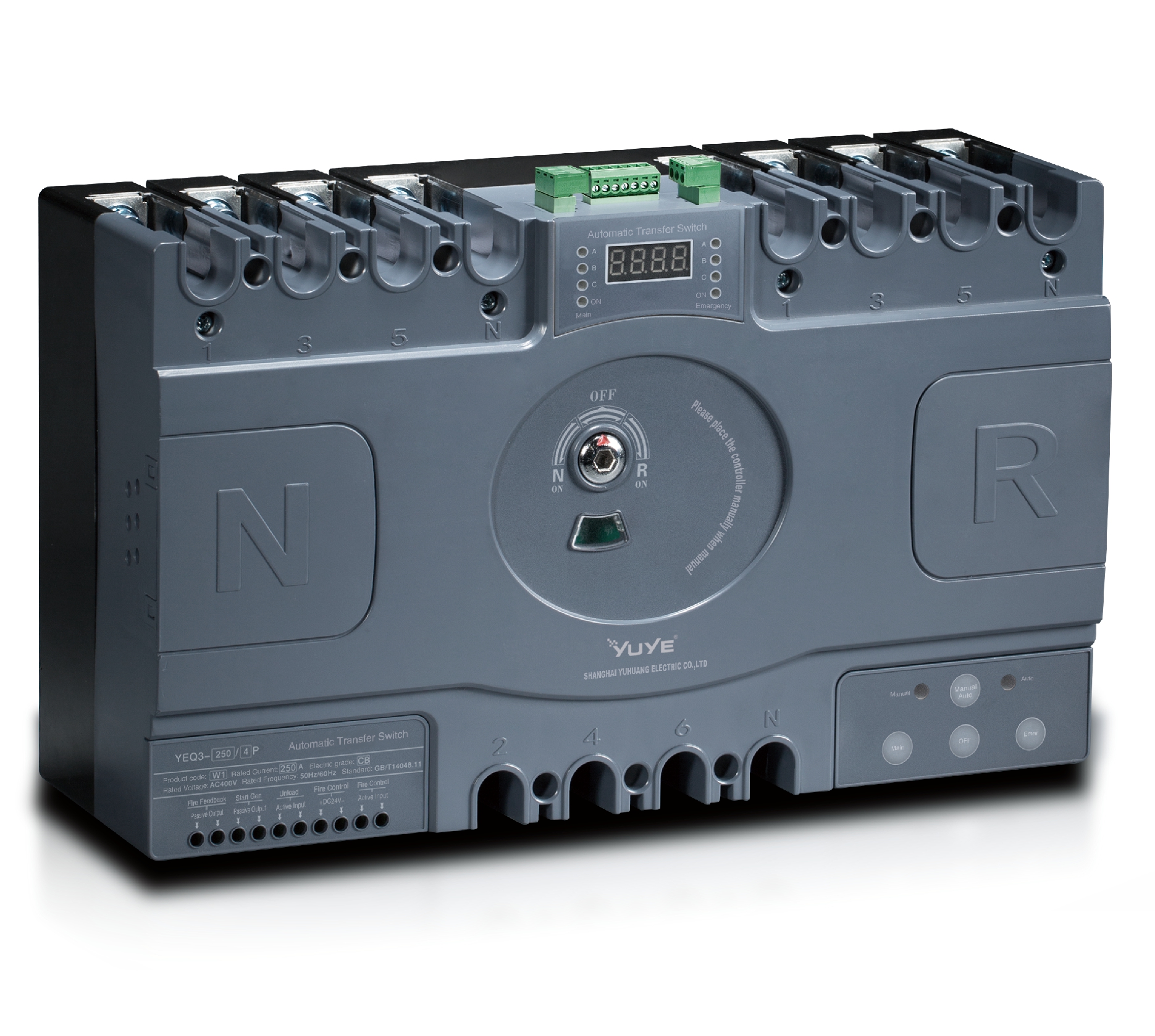 CB ATS YEQ3-125~630W1
 ATS controller Y-700
 ATS Controller Y-700N
 ATS Controller Y-701B
 ATS Controller Y-703N
 ATS Controller Y-800
 ATS Controller W2/W3 Series
 ATS switch Cabinet floor-to-ceiling
 ATS switch cabinet
 JXF-225A power Cbinet
 JXF-800A power Cbinet
 YEM3-125~800 Plastic Shell Type MCCB
 YEM3L-125~630 Leakage Type MCCB
 YEM3Z-125~800 Adjustable Type MCCB
 YEM1-63~1250 Plastic Shell Type MCCB
 YEM1E-100~800 Electronic Type MCCB
 YEM1L-100~630 Leakage Type MCCB
 Miniature circuit breaker YEMA2-6~100
 Miniature circuit breaker YEB1-3~63
 Miniature circuit breaker YEB1LE-3~63
 Miniature circuit breaker YEPN-3~32
 Miniature circuit breaker YEPNLE-3~32
 Miniature circuit breaker YENC-63~125
 Air Circuit Breaker YEW1-2000~6300
 Air Circuit Breaker YEW3-1600
 Load isolation switch YGL-63~3150
 Load Isolation Switch YGL2-63~3150
 Manual Changeover Switch YGL-100~630Z1A
 Manual Changeover Switch YGLZ1-100~3150
 YECPS2-45~125 LCD
 YECPS-45~125 Digital
 CNC Milling/Turning-OEM
 DC relay MDC-300M
 DC Isolation Switch YEGL3D-630


