 PC ATS YECT1-2000G
 PC ATS YES2-63~250GN1
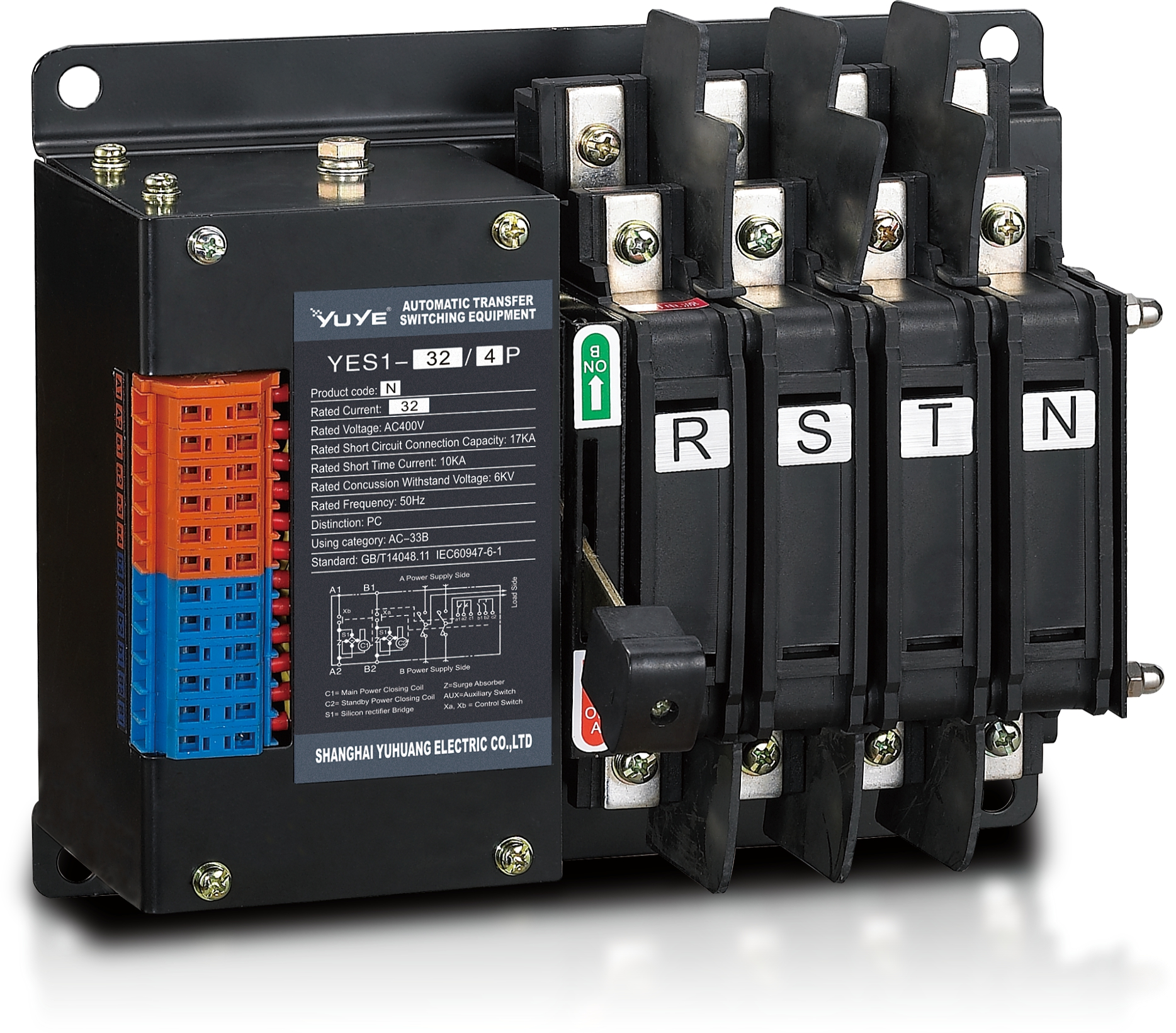 Solenoid-type ATS YES1-32~125N
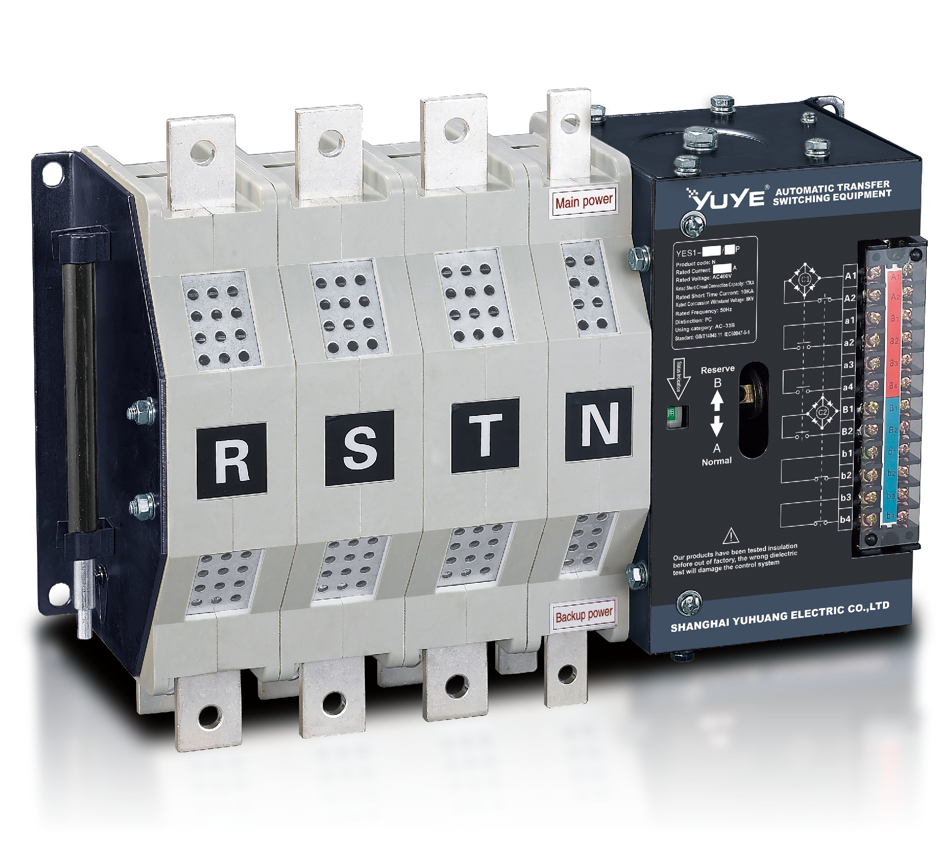 Solenoid-type ATS YES1-250~630N/NT
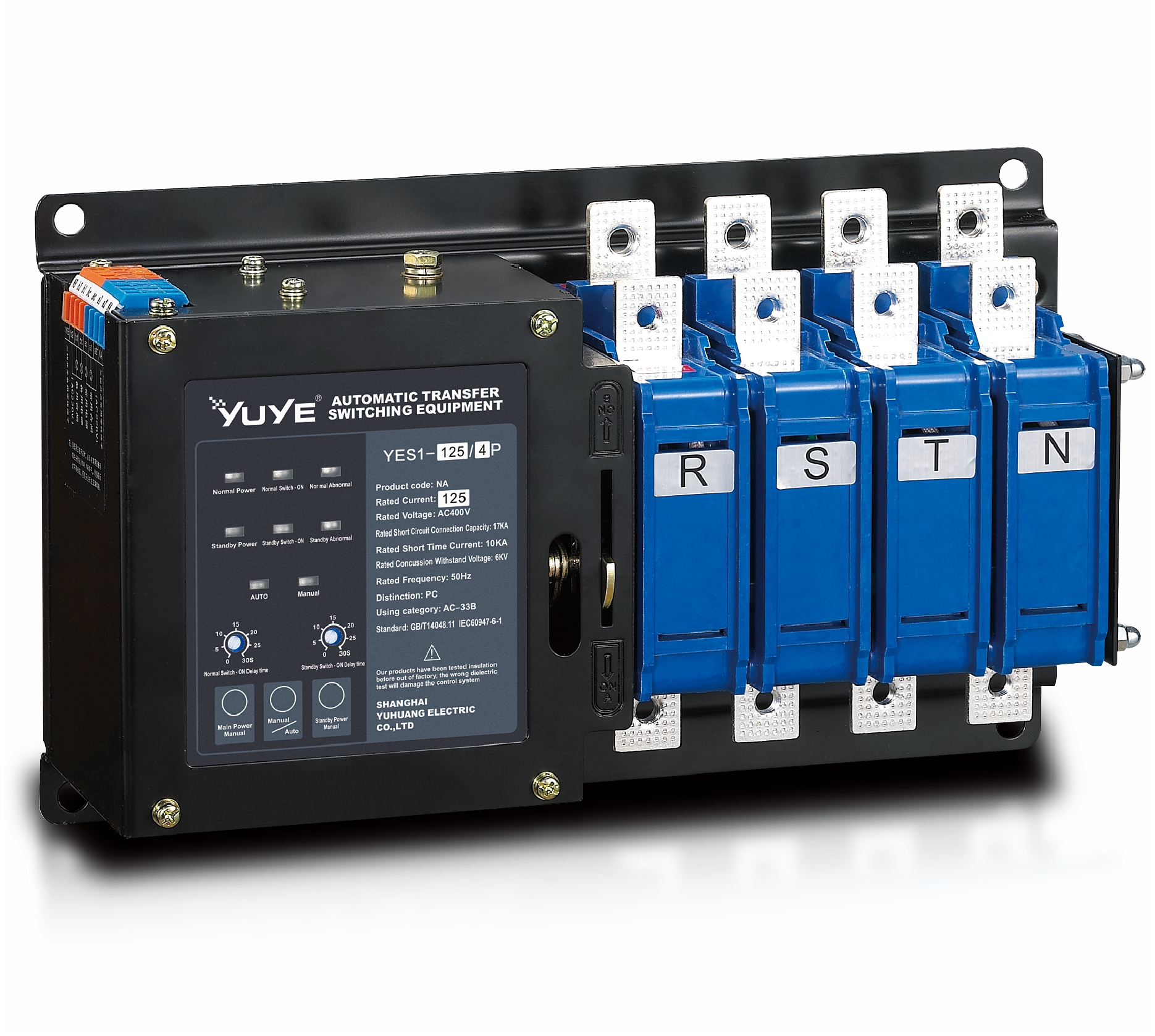 Solenoid-type ATS YES1-32~125NA
 Solenoid-type ATS YES1-63~630SN
 Solenoid-type ATS YES1-1250~4000SN
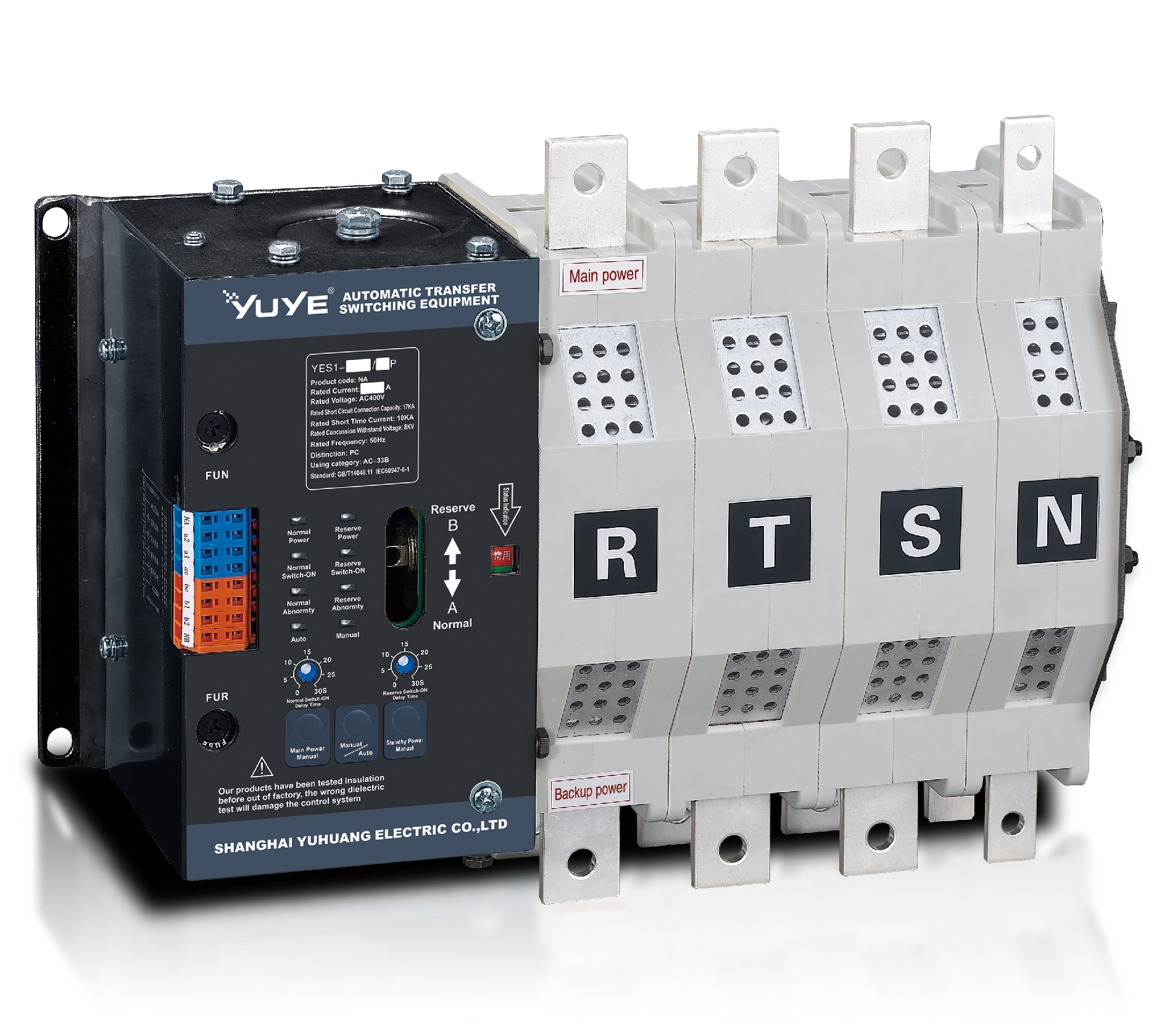 Solenoid-type ATS YES1-250~630NA/NAT
 Solenoid-type ATS YES1-63NJT
 PC ATS YES1-100~1600GN1/GN/GNF
 PC ATS YES1-2000~3200GN/GNF
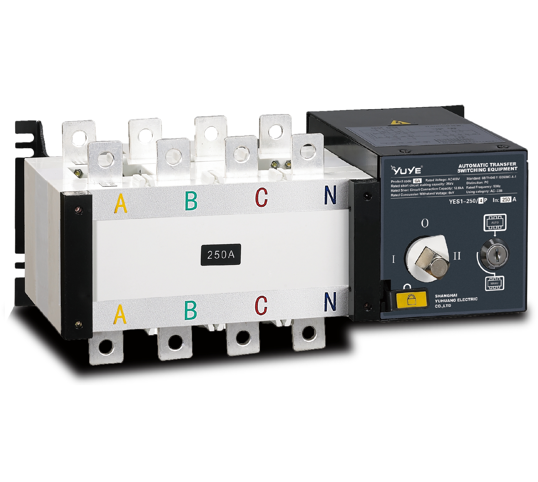 PC ATS YES1-100~3200GA1/GA
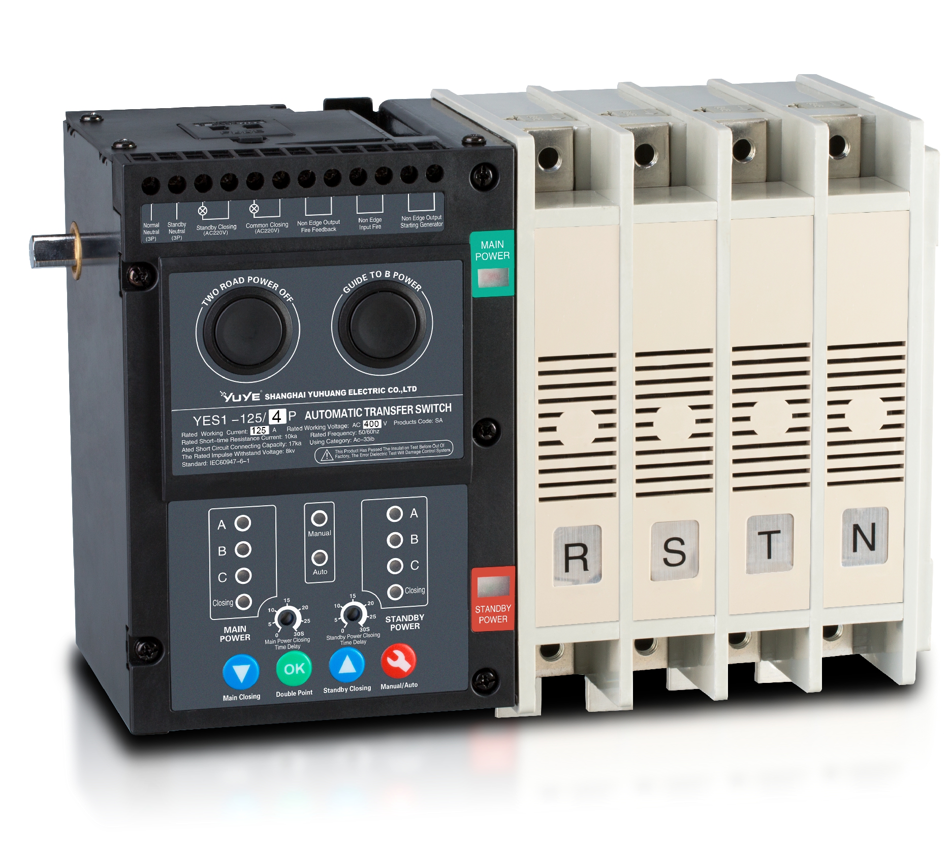 Solenoid-type ATS YES1-63~630SA
 Solenoid-type ATS YES1-63~630L/LA
 Solenoid-type ATS YES1-63~630LA3
 Solenoid-type ATS YES1-63MA
 PC ATS YES1-630~1600M
 PC ATS YES1-3200Q
 Solenoid-type ATS YES1-4000~6300Q
 CB ATS YEQ1-63J
 CB ATS YEQ2Y-63
 CB ATS YEQ3-63W1
 CB ATS YEQ3-125~630W1
 ATS controller Y-700
 ATS Controller Y-700N
 ATS Controller Y-701B
 ATS Controller Y-703N
 ATS Controller Y-800
 ATS Controller W2/W3 Series
 ATS switch Cabinet floor-to-ceiling
 ATS switch cabinet
 JXF-225A power Cbinet
 JXF-800A power Cbinet
 YEM3-125~800 Plastic Shell Type MCCB
 YEM3L-125~630 Leakage Type MCCB
 YEM3Z-125~800 Adjustable Type MCCB
 YEM1-63~1250 Plastic Shell Type MCCB
 YEM1E-100~800 Electronic Type MCCB
 YEM1L-100~630 Leakage Type MCCB
 Miniature circuit breaker YEMA2-6~100
 Miniature circuit breaker YEB1-3~63
 Miniature circuit breaker YEB1LE-3~63
 Miniature circuit breaker YEPN-3~32
 Miniature circuit breaker YEPNLE-3~32
 Miniature circuit breaker YENC-63~125
 Air Circuit Breaker YEW1-2000~6300
 Air Circuit Breaker YEW3-1600
 Load isolation switch YGL-63~3150
 Load Isolation Switch YGL2-63~3150
 Manual Changeover Switch YGL-100~630Z1A
 Manual Changeover Switch YGLZ1-100~3150
 YECPS2-45~125 LCD
 YECPS-45~125 Digital
 CNC Milling/Turning-OEM
 DC relay MDC-300M
 DC Isolation Switch YEGL3D-630
The safe and stable operation of modern power systems relies heavily on core switching equipment—the Load Switch. It enables the secure switching of energized circuits, isolates equipment, minimizes downtime, and safeguards personnel and assets. This comprehensive guide covers selection, installation, maintenance, and supplementary knowledge to help avoid common pitfalls and enhance power system operational efficiency.
I. Selection: Identifying the Right Switch to Fortify Power Safety
1.1 Core Understanding: Definition, Functions, and Key Roles
A Load Switch is a mechanical switch capable of safely connecting, carrying, and disconnecting current while equipment remains energized—distinguishing it from isolating switches that only perform de-energizing operations. Its core functions include: controlling load connection/disconnection, isolating equipment to ensure maintenance safety, and reducing electric shock risks.
1.2 Common Types Explained (Manual/Motorized/Fuse-Combination)
Based on operation methods and functions, they are primarily categorized into three types for different scenarios: Manual Switches: Manually operated with simple structure and low cost, suitable for small-scale scenarios with low automation and infrequent operation. Disadvantage: cannot be remotely controlled.
Motorized Switches: Equipped with electric actuators for remote/automated operation and rapid response. Suitable for large-scale industrial and high-rise building automation scenarios. Drawbacks include complex structure and slightly higher maintenance difficulty. Fuse-Combination Switches: Integrate switching and short-circuit protection functions. Offer high cost-effectiveness for scenarios with stringent safety requirements, eliminating the need for additional protective devices.Selection Principles: Flexibly choose corresponding types based on automation needs, environmental conditions, and safety requirements.
1.3 Key Selection Parameters: Detailed Explanation of Voltage, Current, and Short-Circuit Withstand Capability
Selection hinges on matching equipment parameters with system requirements. Critical parameters include: Rated Voltage: Must not be lower than the system operating voltage to prevent insulation damage, short circuits, and other hazards.
Rated Current: Must match the total circuit load to prevent overheating from overload and contact damage.Short-Circuit Withstand Capacity: Must accommodate the system’s maximum short-circuit current to prevent equipment damage during faults.Breaking Capacity: Must match the system’s fault current to ensure safe circuit disconnection during faults.
1.4 Application Techniques for Different Scenarios (Industrial/Commercial/Critical Infrastructure)
Selection must be tailored to specific scenarios to ensure suitability: Industrial Scenarios: High loads and complex environments. Prioritize switches with high rated current, high protection rating, and strong interference resistance.Commercial Scenarios: Even loads and moderate operation. Select compact, easy-to-operate switches suitable for indoor environments.Critical Infrastructure: Extremely high reliability requirements. Prioritize stable performance and fast switching capability. Configure backup equipment when necessary.
1.5 Selection Pitfalls: Common Misconceptions and Correct Selection Principles
Common Misconceptions: Parameter mismatches, neglecting environmental factors, confusing switch types. Correct Process: Define requirements → Verify parameters → Match application → Check compliance to ensure qualified products are selected.
II. Installation: Standardized Procedures for Stable Switch Operation
2.1 Pre-Installation Preparation (Tools, Environment, and Cable Selection)
Three preparations are essential before installation: Prepare professional wiring, testing, and fastening tools; Maintain a clean, dry installation environment with suitable temperature; Select cables with insulation suitable for the switch’s rated current.
2.2 Standard Installation Steps: Key Points for Wiring, Fastening, and Commissioning
Installation must follow these standards: Secure the switch in a well-ventilated, dry location to ensure stability; Wire according to the sequence “live wire first, neutral wire second; input first, output second”; tighten terminals and ensure proper insulation;
After installation, perform pre-power-up checks, no-load testing, and load testing sequentially to ensure normal operation.
2.3 Installation Environment Adaptation: Temperature, Humidity, and Protection Rating Requirements
Key environmental adaptation points:Select switches suitable for the temperature range and implement high/low-temperature protection;Control environmental humidity and implement moisture-proof measures in damp environments;Select the corresponding IP protection rating based on the scenario to resist dust and moisture corrosion. Select corresponding IP protection ratings for specific scenarios to resist dust and moisture ingress.
2.4 Post-Installation Inspection: Ensure Reliable Connections and Smooth Operation
Conduct comprehensive post-installation checks: Verify terminal tightness, correct wiring, and adequate insulation; Test switch operation for smooth engagement/disengagement and proper indicator light function; Inspect grounding reliability and enclosure integrity to eliminate safety hazards.

III. Maintenance: Regular Care to Extend Switch Lifespan
3.1 Daily Inspection Focus (Appearance, Temperature, Operational Flexibility)
Conduct daily inspections, focusing on: Switch appearance intact with no oxidation or damage; Operating temperature within normal range (≤60°C); Smooth closing/opening action without sticking.
3.2 Periodic Maintenance Process: Cleaning, Testing, and Component Inspection
Monthly Routine Maintenance: Power down and clean switch surfaces and terminals to remove dust; Test breaking capacity, insulation performance, and component operational status; Inspect wear-prone parts such as contacts and springs, replacing any aged or damaged components promptly.
3.3 Common Fault Troubleshooting and Emergency Procedures
Common Faults and Solutions: Poor contact (tighten terminals, clean contacts); Inability to open/close (inspect components, clean and lubricate); Abnormal heating (check load, address contact issues).Emergency Procedures: Immediately de-energize during faults, investigate causes. If on-site resolution is impossible, activate backup switch and contact professionals for repairs. Test and verify functionality after repairs.
3.4 Maintenance Record Standards and Long-Term Management Recommendations
Standardize documentation of inspections, faults, and corrective actions for traceability and analysis. Establish reasonable maintenance cycles, enhance personnel training, stock spare wear parts, and optimize maintenance plans.
IV. Supplementary Section: Core Knowledge and FAQs
4.1 Core Differences from Circuit Breakers
Core Difference: Circuit breakers focus on normal on/off control without overload or short-circuit protection; switches combine switching with fault protection, offering broader applicability. Both are often used in tandem.
4.2 International Safety Standards and Compliance Requirements
Switch selection and use must comply with international standards like IEC 60947 and UL. Verify product certifications and parameter compliance, monitor standard updates, and ensure equipment safety and regulatory adherence.
4.3 High-Frequency FAQ: Common Questions on Selection, Installation, and Maintenance
Selection: Match switch specifications to load parameters; choose types based on automation, environmental, and safety requirements.
Installation: Common faults stem from wiring errors or parameter mismatches—troubleshoot systematically.
Maintenance: Conduct daily inspections and monthly scheduled maintenance; inspect and replace wear-prone components every 6–12 months.
Conclusion
Scientific selection, standardized installation, and regular maintenance are critical to ensuring stable operation of switchgear and power systems. This article details key points throughout the entire process, aiming to help readers master techniques, avoid common pitfalls, maximize switchgear functionality, and ensure efficient and safe power system operation.
In practical applications, adapt to specific scenarios, adhere to international standards, and strengthen scientific management. Subsequent equipment configurations can be optimized based on technological advancements to enhance power management capabilities.
References
- International Electrotechnical Commission (IEC): IEC 60947 series standards
- Underwriters Laboratories (UL): Industrial control equipment and electrical safety standards
- Institute of Electrical and Electronics Engineers (IEEE): Resources related to power distribution and electrical system design