
 PC ATS YECT1-2000G
 PC ATS YES2-63~250GN1
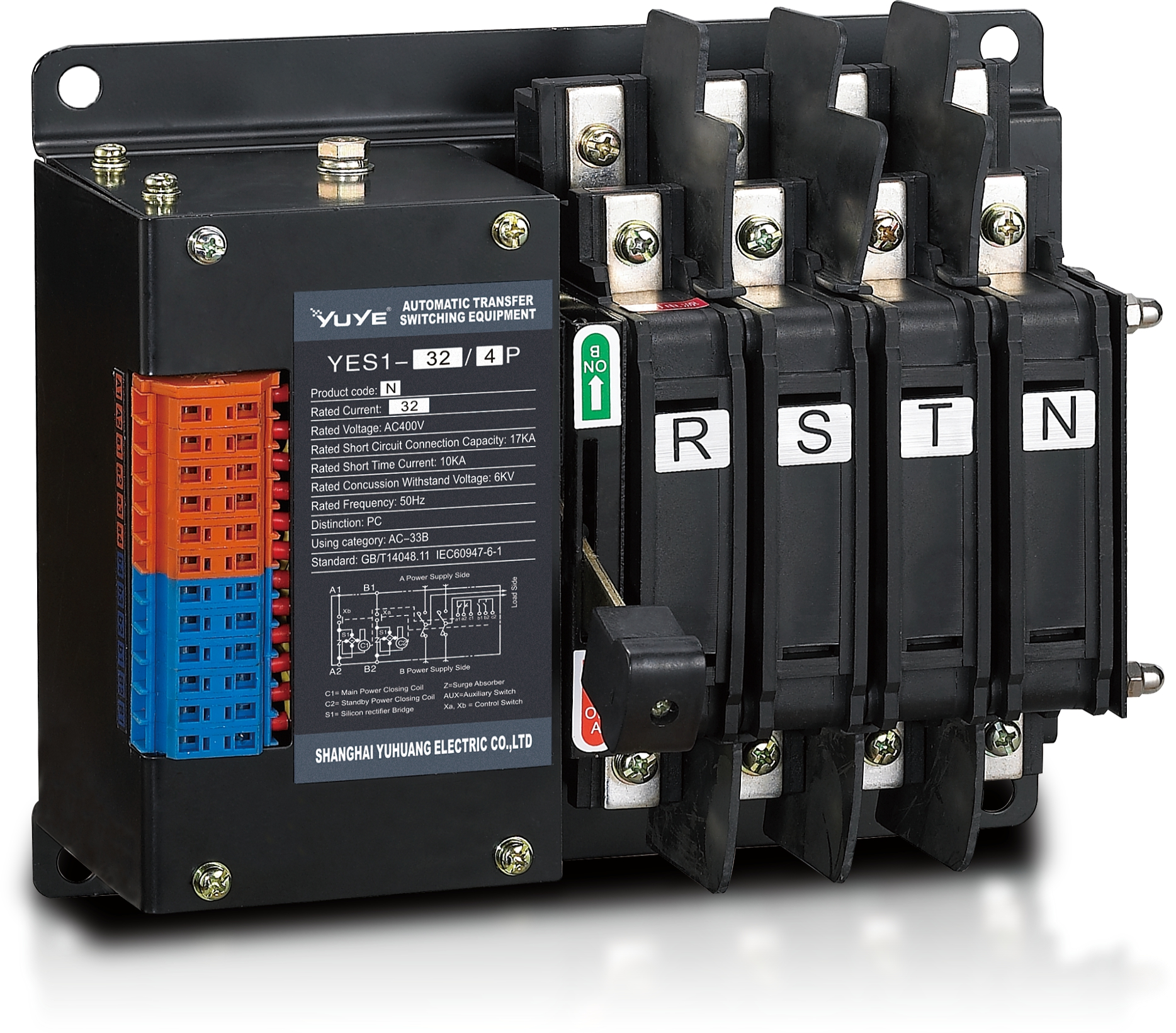 Solenoid-type ATS YES1-32~125N
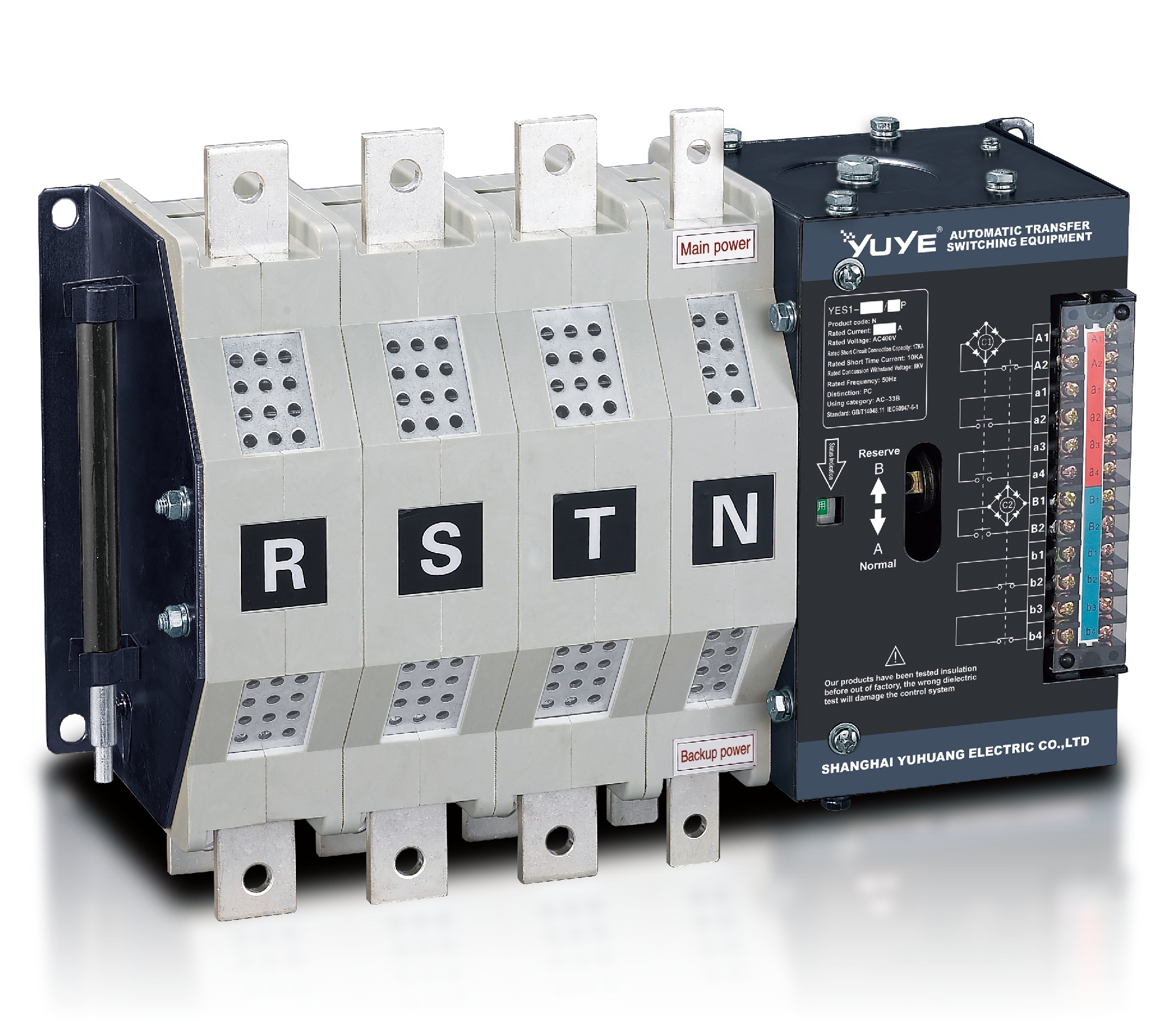 Solenoid-type ATS YES1-250~630N/NT
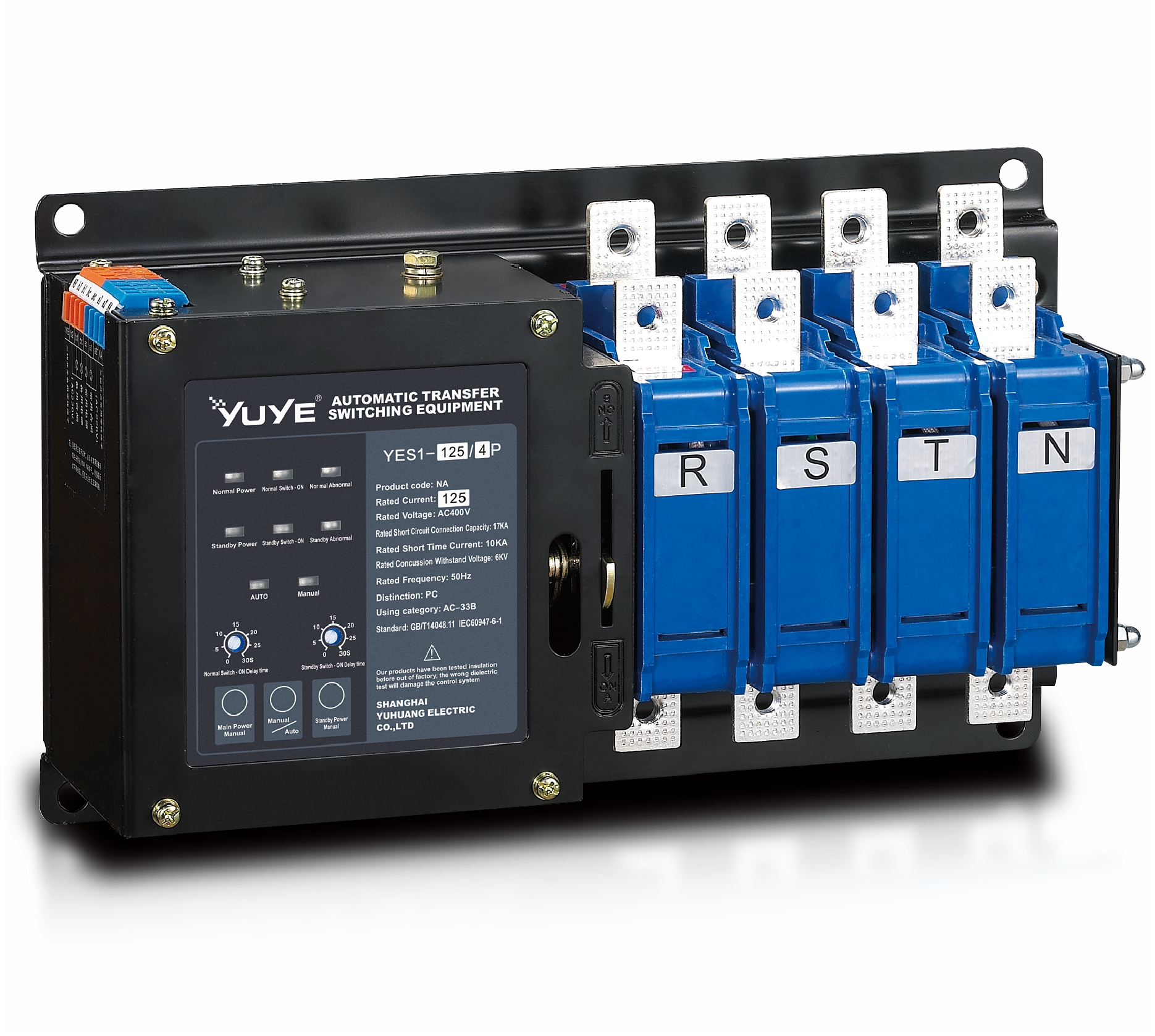 Solenoid-type ATS YES1-32~125NA
 Solenoid-type ATS YES1-63~630SN
 Solenoid-type ATS YES1-1250~4000SN
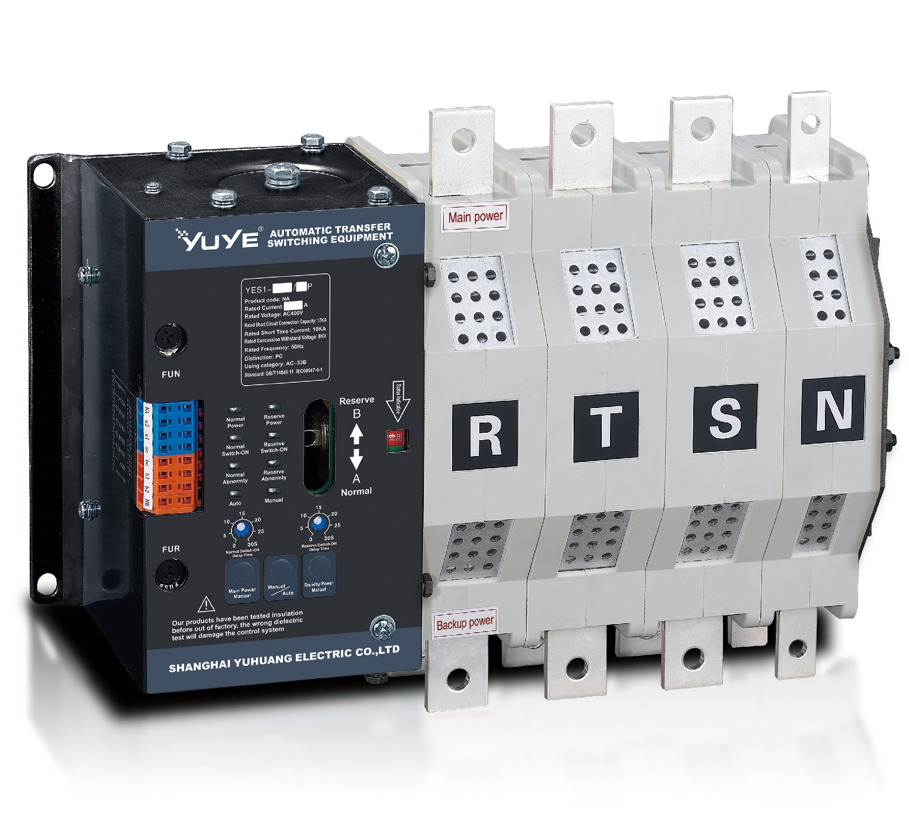 Solenoid-type ATS YES1-250~630NA/NAT
 Solenoid-type ATS YES1-63NJT
 PC ATS YES1-100~1600GN1/GN/GNF
 PC ATS YES1-2000~3200GN/GNF
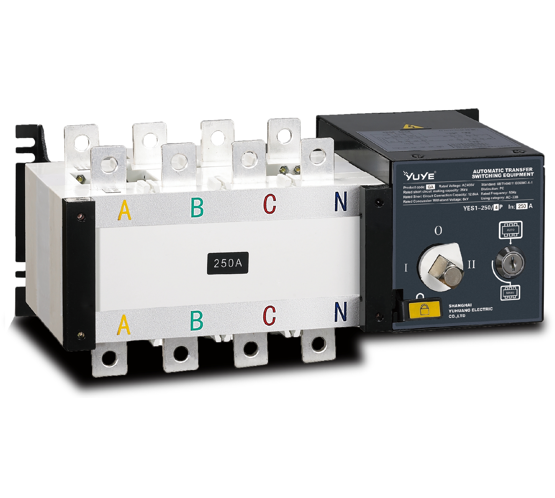 PC ATS YES1-100~3200GA1/GA
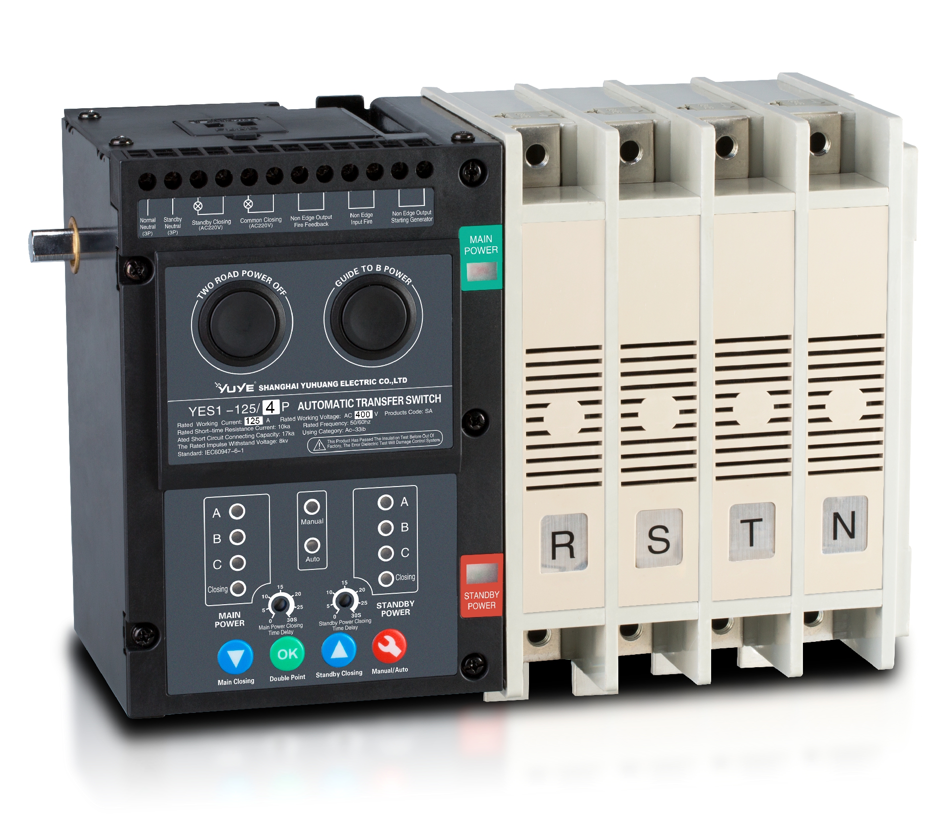 Solenoid-type ATS YES1-63~630SA
 Solenoid-type ATS YES1-63~630L/LA
 Solenoid-type ATS YES1-63~630LA3
 Solenoid-type ATS YES1-63MA
 PC ATS YES1-630~1600M
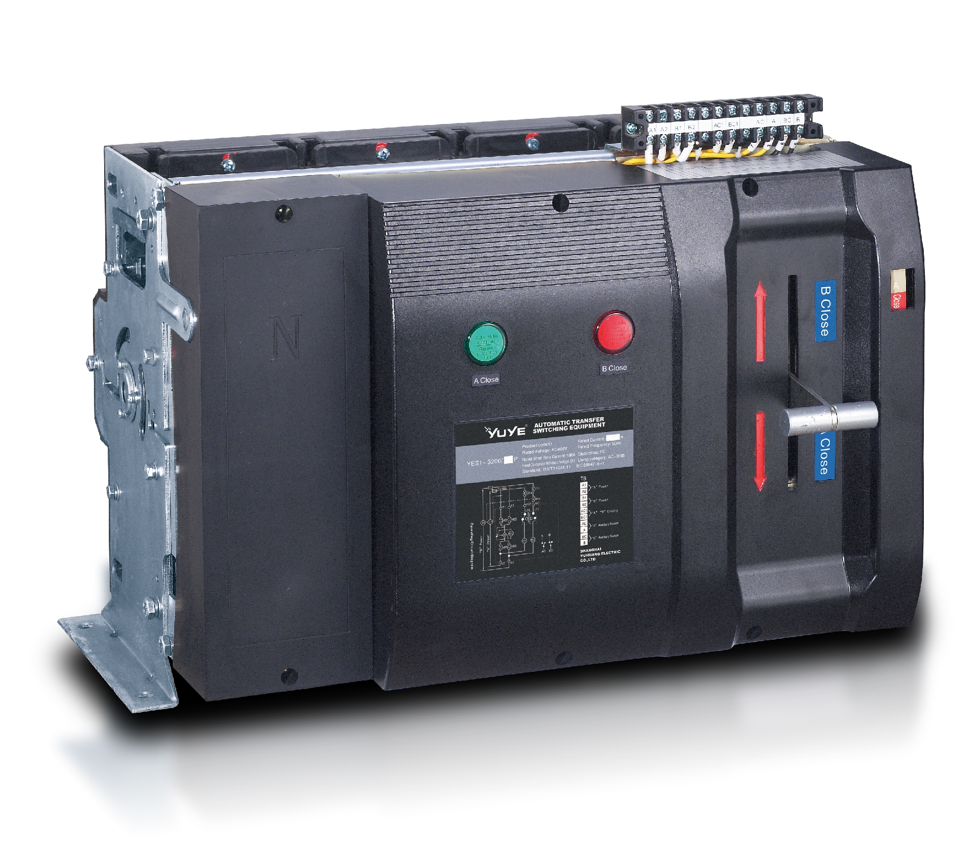 PC ATS YES1-3200Q
 Solenoid-type ATS YES1-4000~6300Q
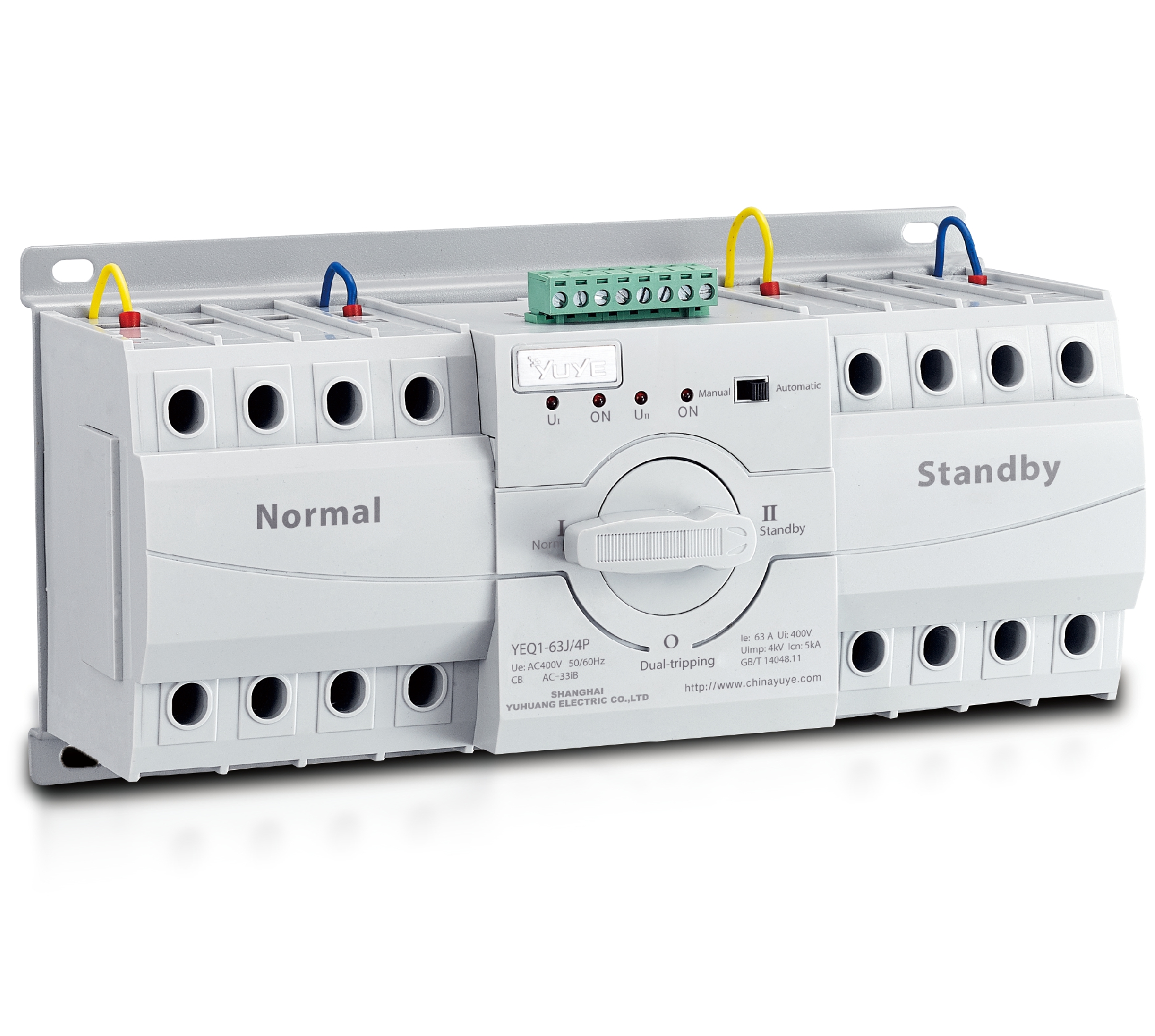 CB ATS YEQ1-63J
 CB ATS YEQ2Y-63
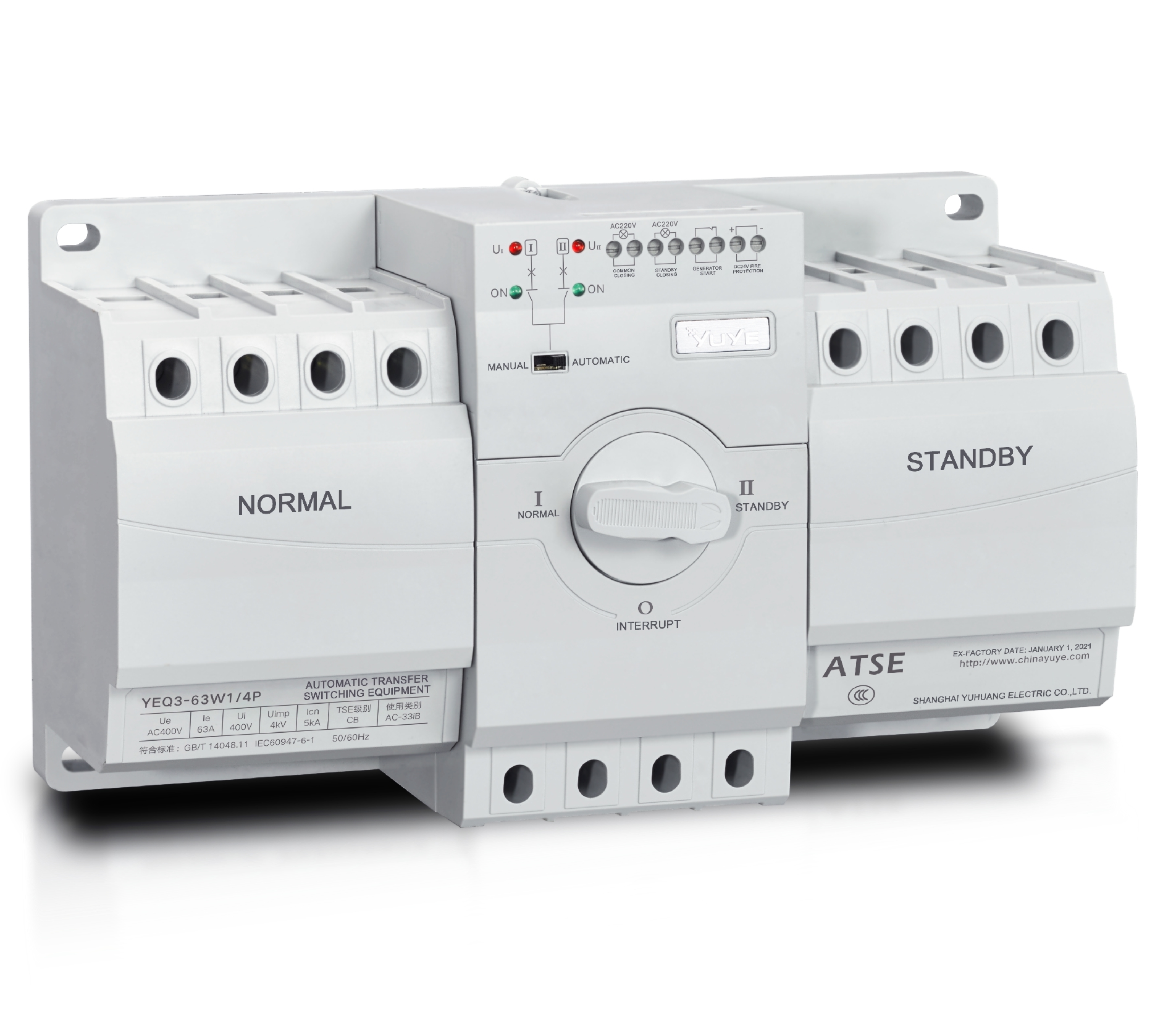 CB ATS YEQ3-63W1
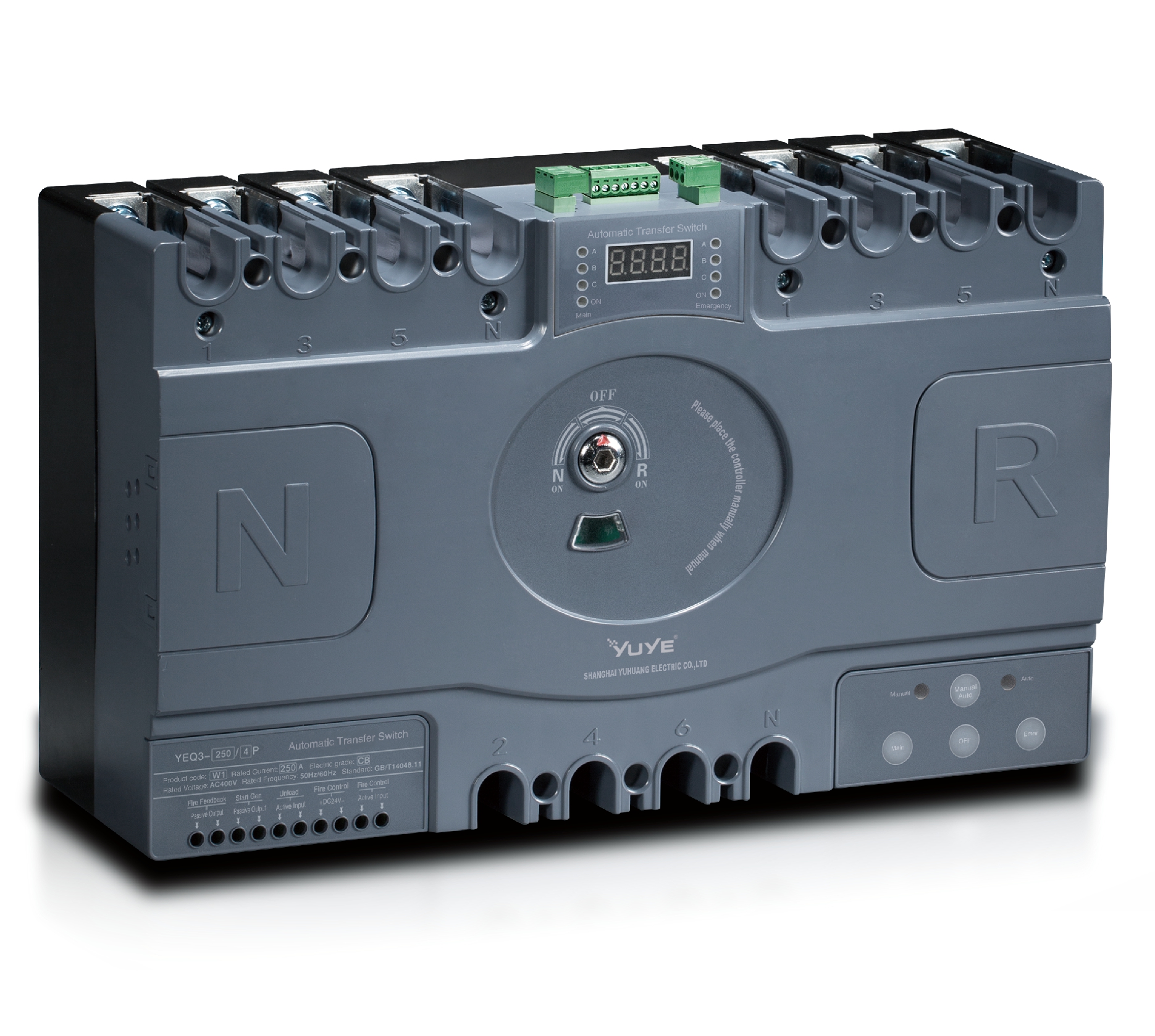 CB ATS YEQ3-125~630W1
 ATS controller Y-700
 ATS Controller Y-700N
 ATS Controller Y-701B
 ATS Controller Y-703N
 ATS Controller Y-800
 ATS Controller W2/W3 Series
 ATS switch Cabinet floor-to-ceiling
 ATS switch cabinet
 JXF-225A power Cbinet
 JXF-800A power Cbinet
 YEM3-125~800 Plastic Shell Type MCCB
 YEM3L-125~630 Leakage Type MCCB
 YEM3Z-125~800 Adjustable Type MCCB
 YEM1-63~1250 Plastic Shell Type MCCB
 YEM1E-100~800 Electronic Type MCCB
 YEM1L-100~630 Leakage Type MCCB
 Air Circuit Breaker YEW1-2000~6300
 Air Circuit Breaker YEW3-1600
 Miniature circuit breaker YEMA2-6~100
 Miniature circuit breaker YEB1-3~63
 Miniature circuit breaker YEB1LE-3~63
 Miniature circuit breaker YEPN-3~32
 Miniature circuit breaker YEPNLE-3~32
 Miniature circuit breaker YENC-63~125
 Load isolation switch YGL-63~3150
 Load Isolation Switch YGL2-63~3150
 DC relay YDC-P20
 DC relay YDC-P250
 DC relay YDC-P400
 DC relay MDC-300M
 DC relay YDC-M400
 DC Isolation Switch YEGL3D-630
 YECPS2-45~125 LCD
 YECPS-45~125 Digital
 CNC Milling/Turning-OEM
I. Introduction
Low-voltage dual power switching systems rely heavily on automatic transfer switches to maintain uninterrupted power supply. In industrial facilities, commercial buildings and public power distribution stations, stable switching performance directly affects operational safety and continuity. As a core power switching component, 4P ATS may develop various malfunctions after long-term operation, frequent switching actions or irregular installation. Common issues include delayed switching, structural jamming and circuit heating, which can easily lead to equipment shutdown and electrical hazards if not handled properly.
Effective fault diagnosis and timely repair can greatly reduce system downtime and lower maintenance costs. This article discusses typical device failures, standard pre-check rules, step-by-step troubleshooting procedures, and long-term prevention methods, providing practical technical guidance for on-site electrical maintenance work.
II. Typical Operational Faults Frequently Found in 4P ATS Devices
During daily operation, automatic transfer switches often exhibit several repeatable abnormal behaviors. The most common faults include unresponsive automatic switching, accidental mis-switching between main and backup power, excessive operating noise, continuous surface heating, indicator light anomalies, and failure to complete automatic reset.
Most faults stem from similar root causes. Unstable input power signals, aging internal mechanical linkage structures, mismatched controller parameters, loose wiring terminals and degraded electronic components are the main inducements. In many cases, multiple factors work together to cause intermittent failures that are difficult to reproduce and locate.
These seemingly minor abnormalities carry obvious risks. Unplanned switching may cause sudden power interruption, while poor contact and overheating can burn internal circuits. Long-term untreated faults will gradually deteriorate and eventually lead to complete system power failure.
III. Pre-Diagnosis Preparation and Safety Inspection Rules
Before any fault detection and repair work, standardized preparation is essential to ensure personal safety and avoid secondary equipment damage. Maintenance staff must confirm complete power off of both main and backup power circuits, inspect insulation tools, and check the overall appearance of the device for obvious deformation, burning marks or damaged wiring.
All diagnosis operations must follow strict safety specifications. Live-line blind detection is prohibited, and short-circuit prevention measures must be prepared in advance. Operators should wear standard insulating protective equipment and keep the working area dry and tidy.
Professional maintenance usually follows the principle of static inspection first and dynamic testing later. Check external wiring and structural conditions statically, and conduct power-on function tests only after no obvious hidden dangers are confirmed, which greatly improves diagnosis accuracy and safety.

IV. Step-by-Step Troubleshooting for Power Switching Failures
Switching failure is the most frequent problem of automatic transfer equipment, and it can be diagnosed through fixed step-by-step procedures. First, technicians need to check external power conditions, verify whether the voltage and phase sequence of main power and backup power are normal, and rule out power supply side failures.
After confirming normal power input, inspect internal circuits and terminals. Check all wiring terminals for looseness, virtual connection and oxidation, and replace aging wires. Meanwhile, verify the controller’s internal parameter settings, including switching delay threshold and automatic recovery mode, to eliminate configuration errors.
Finally, conduct manual and automatic switching tests separately. By simulating power failure and power recovery scenarios, technicians can accurately distinguish mechanical structural faults from electrical signal faults and implement targeted repair solutions according to actual test results.
V. Diagnosis and Fixes for Wiring and Mechanical Abnormalities
Wiring problems are one of the primary causes of repeated device failures. Common issues include wrong phase sequence connection, loose terminal screws, insufficient wire diameter for high-current loads and unstandardized grounding. These problems usually lead to unstable operation, frequent tripping and continuous equipment heating. The solution is to rearrange the wiring strictly according to standard diagrams and reinforce all connection terminals.
Mechanical failures mainly occur after long-term use. Internal linkage wear, rotating shaft jamming and insufficient reset elasticity will cause inflexible switching and incomplete closure. For such faults, partial disassembly inspection is required to check component wear and structural offset.
For severely worn parts, direct replacement is the most reliable solution. After replacement, calibrate the mechanical closing position and test the switching flexibility repeatedly to ensure the mechanical structure can operate smoothly under long-term load conditions.
VI. Post-Repair Testing and Long-Term Fault Prevention Strategies
Repair work is not completed after simple troubleshooting. Comprehensive post-repair testing must be carried out, including circuit insulation resistance testing, no-load switching testing and simulated full-load operation verification, to ensure all hidden faults are completely eliminated.
Daily standardized maintenance is the key to reducing failure rates. Regular cleaning of internal dust, terminal tightening inspection and parameter calibration can effectively avoid most intermittent faults. Maintaining stable operating environment temperature and humidity also helps extend equipment service life.
Standardized installation, reasonable load matching and periodic inspection form a complete long-term prevention system, which can keep the overall performance of 4P ATS stable for a long time and reduce unnecessary maintenance costs.
VII. Conclusion
Automatic transfer switch failures are mostly caused by wiring irregularities, mechanical aging and parameter mismatching. Through standardized pre-inspection, step-by-step diagnosis and classified repair, most common faults can be quickly resolved. Scientific maintenance and standardized operation can effectively avoid repeated failures.
As an important guarantee for continuous power supply, regular fault detection and maintenance of 4P ATS is essential for the safe and stable operation of low-voltage power distribution systems.
References
1. National Electrical Installation Standards. Low-Voltage Power Distribution Equipment Maintenance Specification, 2024.
2. Electrical Equipment Safety Testing Association. Automatic Transfer Switch Fault Diagnosis and Maintenance Guidelines.
3. Industrial Power Distribution Design Manual. Common Fault Analysis of Dual Power Switching Devices.
4. Low-Voltage Electrical Engineering Committee. Operation Inspection and Calibration Standards for ATS Devices.
FAQ
Q1: Why does the device fail to switch automatically?
A1: It is usually caused by abnormal power signal, incorrect controller parameters or loose internal wiring. Users can check power supply status and reset switching parameters first.
Q2: What causes continuous heating during ATS operation?
A2: Heating mostly results from loose terminals, insufficient wire diameter or long-term overload operation. Tightening wiring and matching appropriate load current can solve the problem.
Q3: Is mechanical jamming repairable on site?
A3: Minor jamming can be fixed by cleaning dust and calibrating structure. Severe wear requires professional replacement of internal mechanical parts.
Q4: How to avoid repeated ATS faults?
A4: Follow standardized installation rules, avoid long-term overloads, conduct regular dust cleaning and terminal inspection, and calibrate parameters periodically.
Q5: Is power-off operation mandatory for fault diagnosis?
A5: Yes. Except for signal testing, all disassembly, wiring and maintenance work must be performed under power-off status to ensure construction safety.
