
 PC ATS YECT1-2000G
 PC ATS YES2-63~250GN1
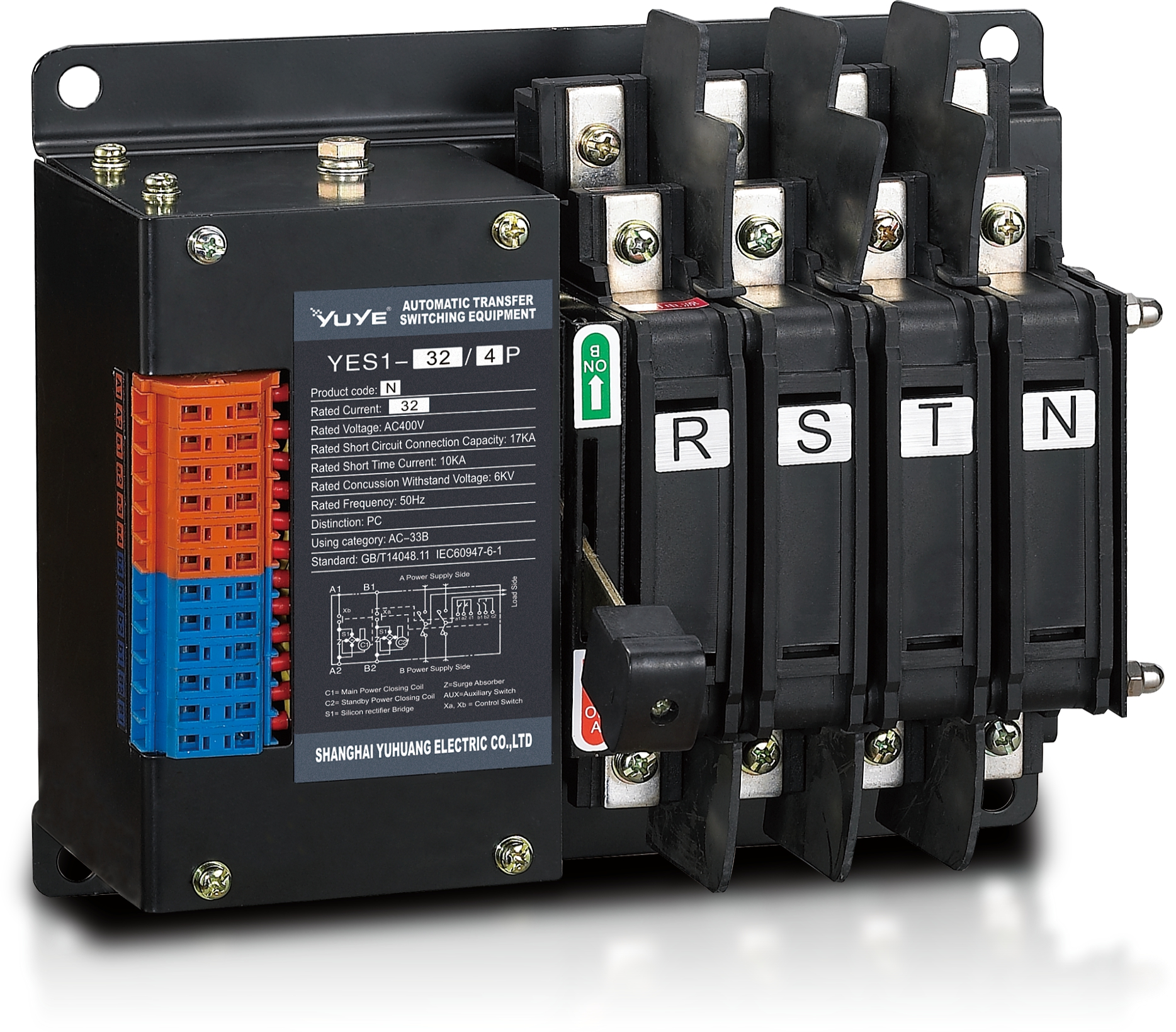 Solenoid-type ATS YES1-32~125N
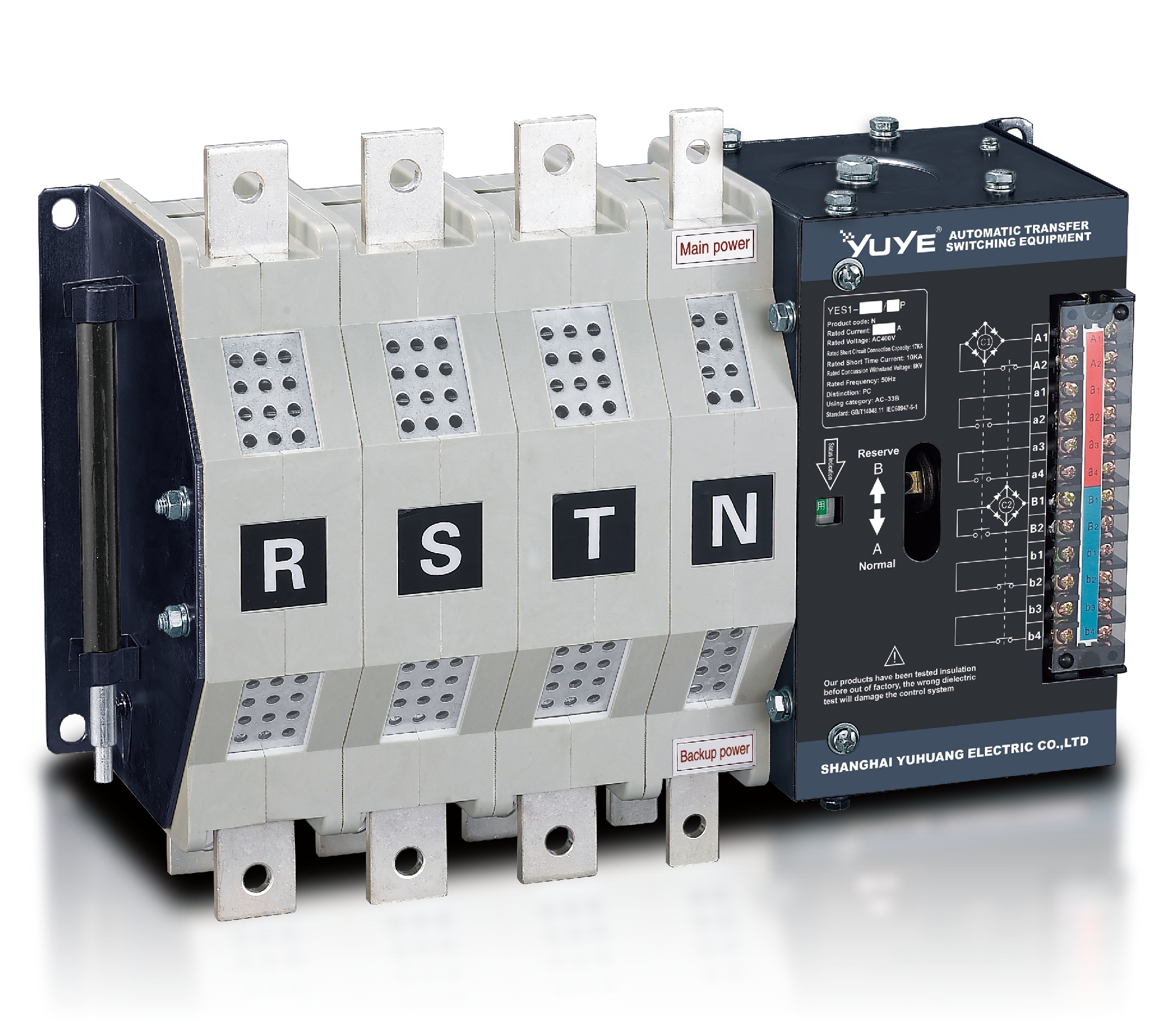 Solenoid-type ATS YES1-250~630N/NT
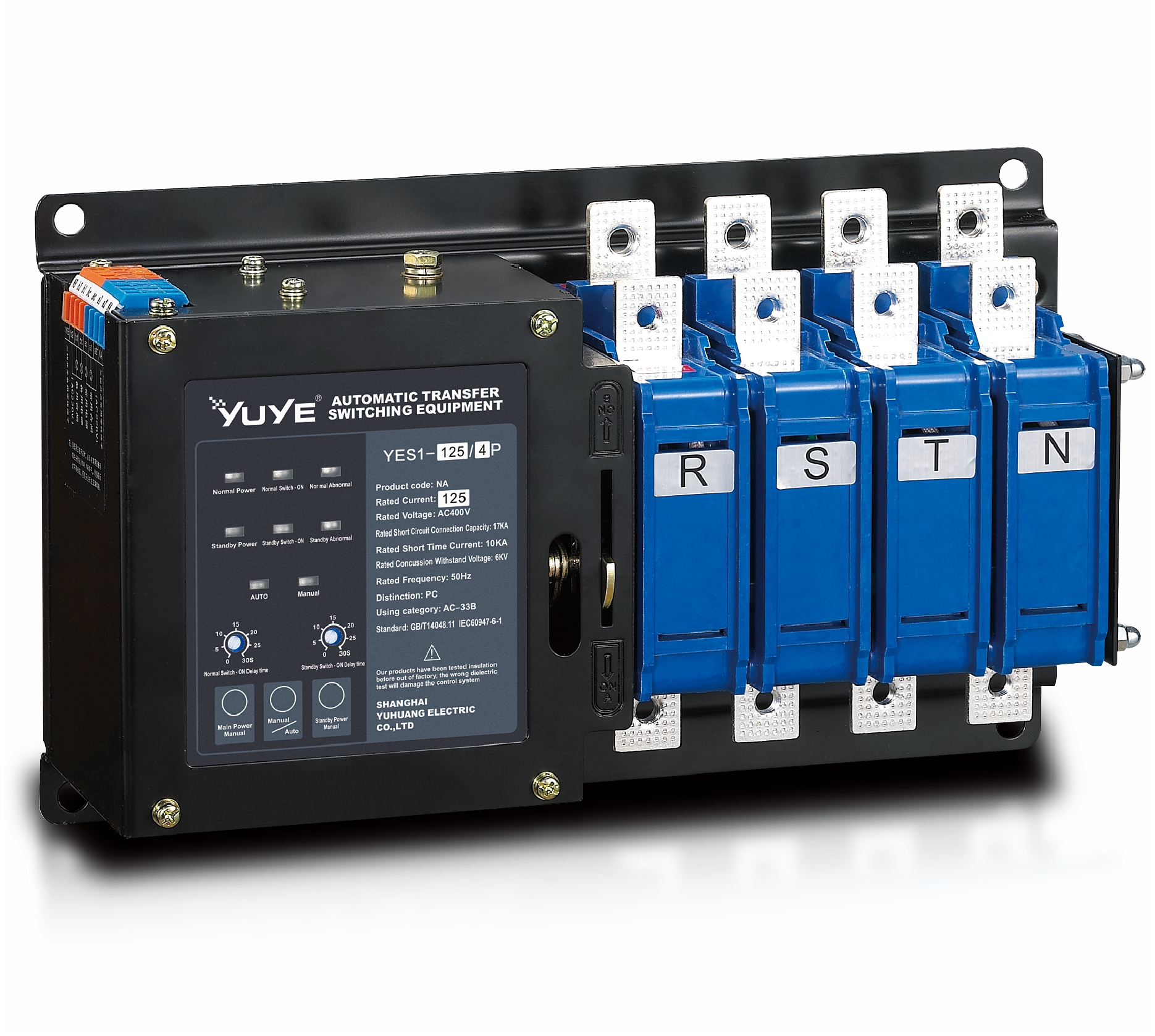 Solenoid-type ATS YES1-32~125NA
 Solenoid-type ATS YES1-63~630SN
 Solenoid-type ATS YES1-1250~4000SN
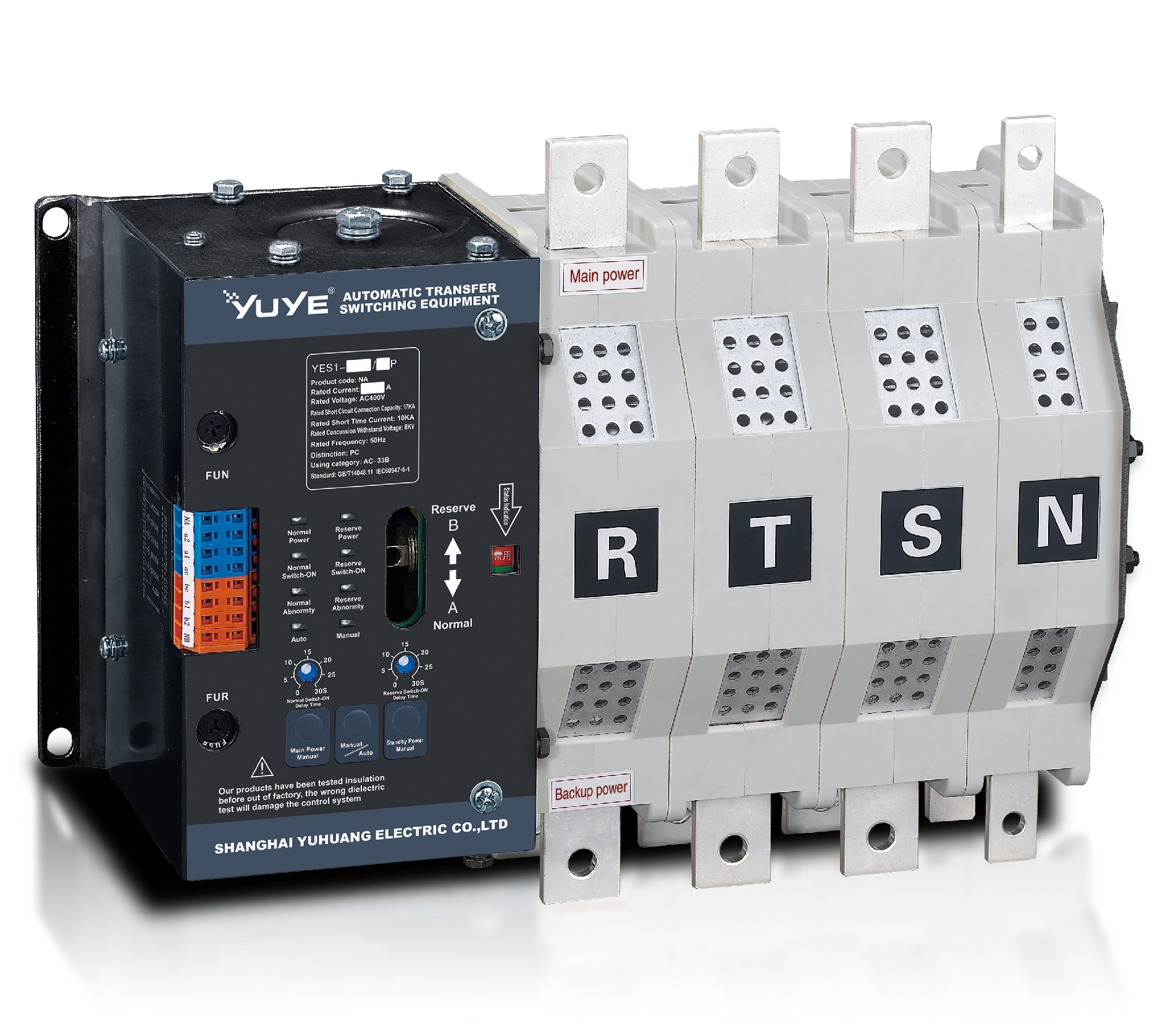 Solenoid-type ATS YES1-250~630NA/NAT
 Solenoid-type ATS YES1-63NJT
 PC ATS YES1-100~1600GN1/GN/GNF
 PC ATS YES1-2000~3200GN/GNF
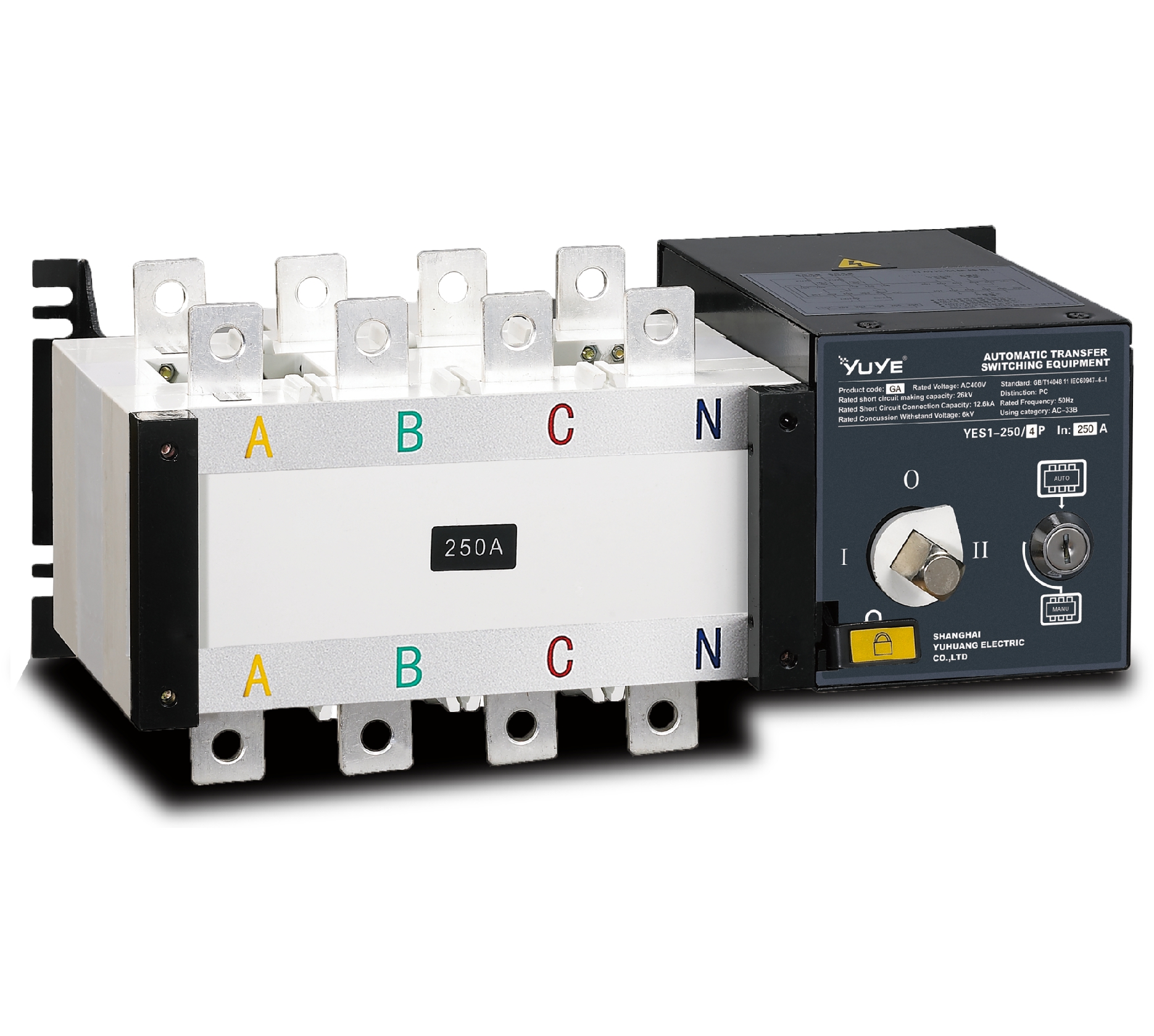 PC ATS YES1-100~3200GA1/GA
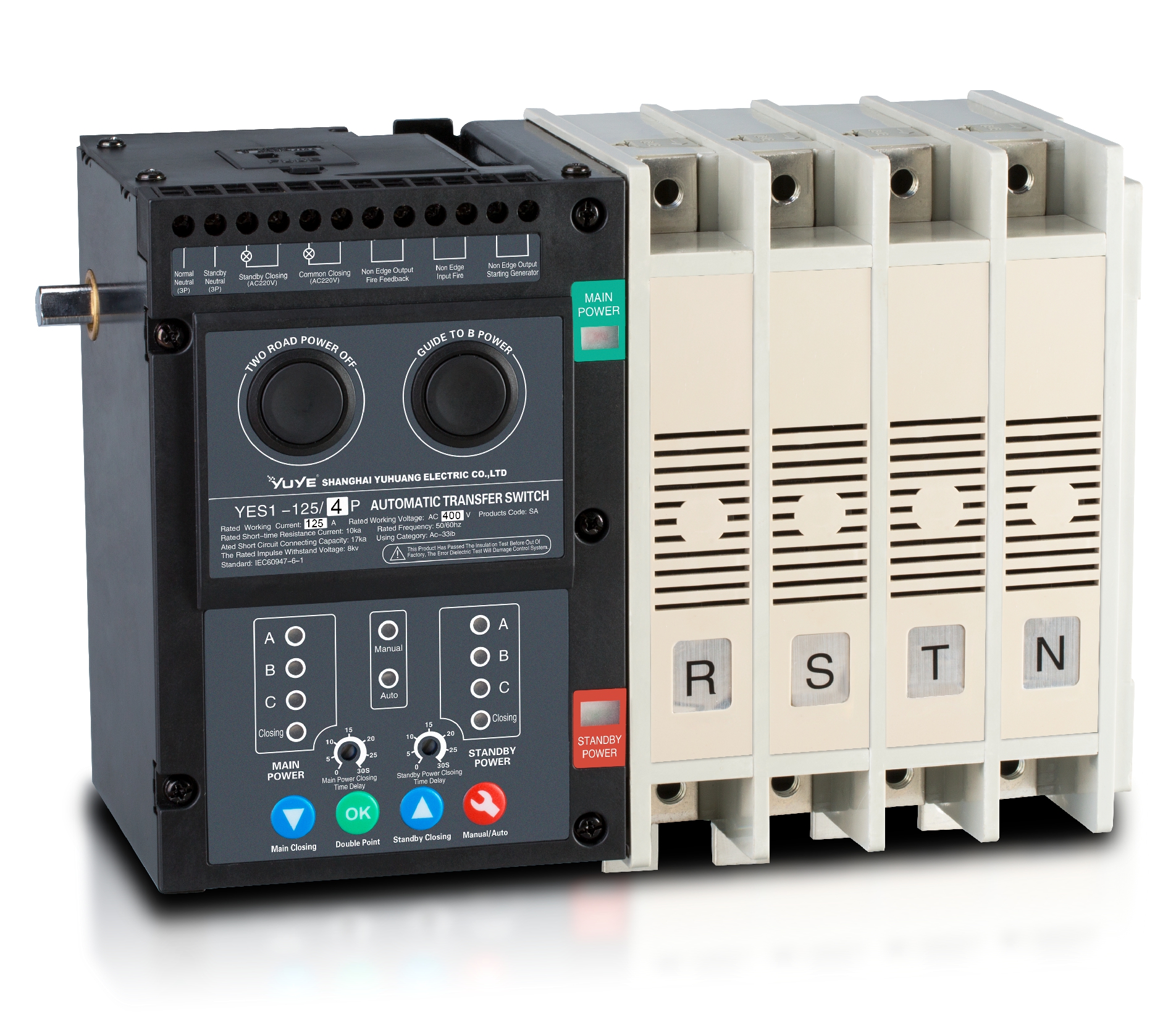 Solenoid-type ATS YES1-63~630SA
 Solenoid-type ATS YES1-63~630L/LA
 Solenoid-type ATS YES1-63~630LA3
 Solenoid-type ATS YES1-63MA
 PC ATS YES1-630~1600M
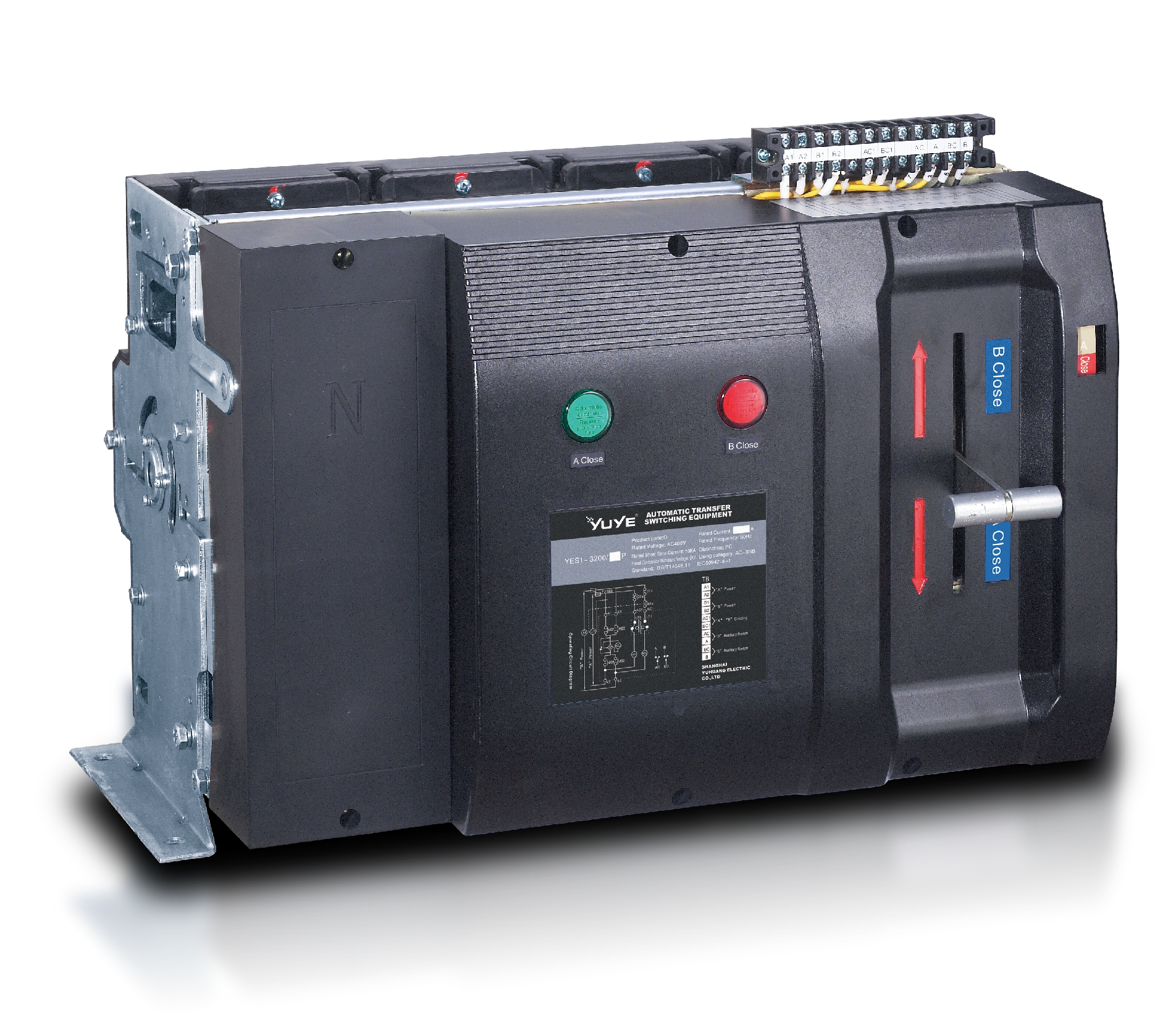 PC ATS YES1-3200Q
 Solenoid-type ATS YES1-4000~6300Q
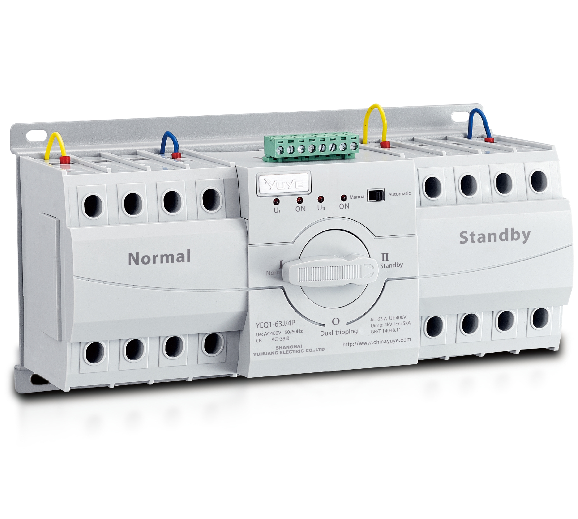 CB ATS YEQ1-63J
 CB ATS YEQ2Y-63
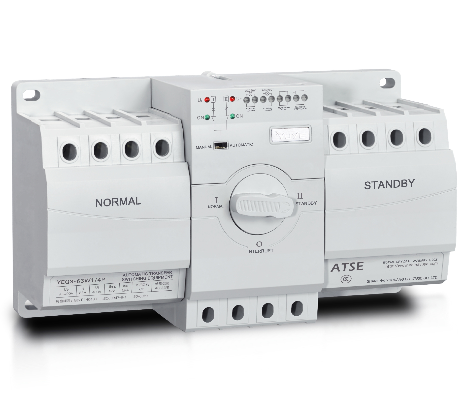 CB ATS YEQ3-63W1
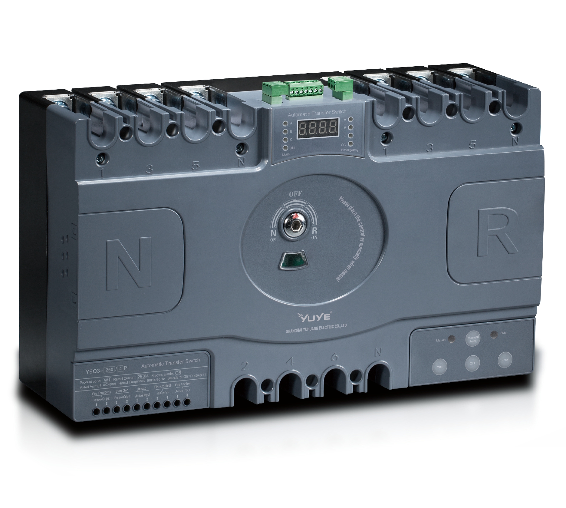 CB ATS YEQ3-125~630W1
 ATS controller Y-700
 ATS Controller Y-700N
 ATS Controller Y-701B
 ATS Controller Y-703N
 ATS Controller Y-800
 ATS Controller W2/W3 Series
 ATS switch Cabinet floor-to-ceiling
 ATS switch cabinet
 JXF-225A power Cbinet
 JXF-800A power Cbinet
 YEM3-125~800 Plastic Shell Type MCCB
 YEM3L-125~630 Leakage Type MCCB
 YEM3Z-125~800 Adjustable Type MCCB
 YEM1-63~1250 Plastic Shell Type MCCB
 YEM1E-100~800 Electronic Type MCCB
 YEM1L-100~630 Leakage Type MCCB
 Air Circuit Breaker YEW1-2000~6300
 Air Circuit Breaker YEW3-1600
 Miniature circuit breaker YEMA2-6~100
 Miniature circuit breaker YEB1-3~63
 Miniature circuit breaker YEB1LE-3~63
 Miniature circuit breaker YEPN-3~32
 Miniature circuit breaker YEPNLE-3~32
 Miniature circuit breaker YENC-63~125
 Load isolation switch YGL-63~3150
 Load Isolation Switch YGL2-63~3150
 DC relay YDC-P20
 DC relay YDC-P250
 DC relay YDC-P400
 DC relay MDC-300M
 DC relay YDC-M400
 DC Isolation Switch YEGL3D-630
 YECPS2-45~125 LCD
 YECPS-45~125 Digital
 CNC Milling/Turning-OEM
I. Introduction
Standard installation is essential for the stable operation of low-voltage automatic transfer switches. Proper mounting and wiring ensure reliable switching between main and backup power, avoiding equipment faults and safety risks. As a key power switching device, 4P ATS requires standardized installation to prevent poor contact, overheating and switching failures, which effectively stabilizes the entire power distribution system.
Different application scenarios require matched installation methods. Common installation types include wall mounting, cabinet integration and DIN-rail mounting. This article summarizes mainstream installation solutions, standard wiring rules and post-installation commissioning steps to provide practical guidance for on-site electrical construction and maintenance work.
II. Common Mounting Types for Standard 4P ATS Units
There are three common installation methods for standard automatic transfer switches: wall-mounted, cabinet integrated panel mounting, and DIN-rail mounting. Each method fits different space conditions, load levels and maintenance needs, covering most civil, commercial and industrial power distribution scenarios.
Wall-mounted installation is simple and flexible for independent power distribution spaces without fixed cabinets. Cabinet integrated installation features neat layout and high standardization, widely adopted in industrial and commercial distribution systems. DIN-rail mounting is compact, mainly used for small-current terminal circuits with light loads.
In practical engineering, wall mounting is easy to construct but occupies wall space; cabinet integration facilitates daily maintenance; DIN-rail mounting offers high flexibility but only supports small-specification devices. Technicians should select installation modes based on actual site conditions and design requirements.
III. Step-by-Step Procedures for Wall-Mounted Installation
Wall-mounted installation is commonly used in medium and small distribution rooms and independent power supply systems. The whole process includes pre-installation preparation, fixed mounting and final inspection, with clear standard requirements for each step.
Before installation, choose a dry, clean and stable position away from vibration sources. Inspect the device appearance and complete tool preparation, reserving enough space for heat dissipation and daily operation.
Standard steps include positioning and drilling holes, fixing mounting brackets with expansion bolts, and installing and fastening the device. Keep the equipment vertical and level to avoid internal component stress and poor contact caused by long-term tilt.
Check wall bearing capacity to support long-term equipment weight. Reasonable heat dissipation gaps must be reserved to prevent heat accumulation, overheating protection and switching abnormalities.

IV. Cabinet Integrated Installation: Rules and Precautions
Cabinet integrated installation refers to embedded panel mounting, which is the mainstream solution for industrial equipment, data centers and large commercial distribution cabinets. It realizes centralized and standardized power distribution management.
Before installation, verify that cabinet size and opening dimensions match the device parameters. Arrange internal components reasonably and maintain safe spacing between the transfer switch and other electrical parts to avoid electromagnetic interference and facilitate later maintenance.
Take anti-vibration measures during installation to prevent loose terminals and switching errors. Ensure smooth cabinet ventilation and heat dissipation, and equip auxiliary heat dissipation accessories for high-current devices to guarantee stable load operation.
Integrated cabinet installation improves system neatness and reduces line failure rates, making it the preferred option for most centralized power distribution scenarios.
V. Key Wiring Standards Across All Installation Methods
All installation methods follow unified wiring standards, which are critical to equipment safety. Standard wiring effectively avoids phase errors, poor neutral contact and grounding faults that threaten system stability.
Connect phase, neutral and grounding wires strictly according to device labels without wrong or missing connections. Select wire diameter matching the rated current, and adopt thicker wires for high-current models to avoid overheating and voltage drop.
Keep wiring tidy and firm with standard terminal fastening torque. Install anti-loosening accessories at key connection points to prevent terminal looseness during long-term operation.
Avoid common errors such as disordered neutral wiring, confused main and backup power lines, and missing grounding. Check all lines carefully after wiring to eliminate hidden dangers.
VI. Post-Installation Inspection & Commissioning Checklist
Installation completion cannot guarantee normal operation. Comprehensive inspection and commissioning are necessary to verify installation quality and overall system reliability.
First, conduct visual inspection to confirm firm installation, tidy wiring and no exposed live parts. Then complete electrical tests including circuit continuity and insulation resistance detection to rule out short circuit and open circuit faults.
After static inspection, test manual and automatic switching functions. Simulate power failure and recovery to verify sensitive, stable and delay-free switching performance.
Qualified test results complete the installation acceptance. Daily maintenance should include regular inspection of installation firmness and terminal tightness to maintain long-term stable operation.
VII. Conclusion
In summary, the installation of 4P ATS covers three mainstream methods suitable for different scenarios. Constructors shall select proper mounting types according to site space, load parameters and design standards, and comply with unified wiring and commissioning specifications.
Standardized installation and strict inspection effectively reduce failure rates and extend equipment service life. Non-standard construction easily causes hidden risks and affects power switching performance.
Matching reasonable installation solutions for industrial, commercial and civil power systems is critical to safe and efficient operation. Scientific installation management greatly improves the working stability of 4P ATS and ensures continuous and reliable power supply for the whole distribution system.
References
1. National Electrical Manufacturers Association. Installation Guidelines for Automatic Transfer Switches, 2024.
2. Low-Voltage Electrical Installation Engineering Construction Specification. General Technical Requirements for Power Switching Equipment Installation.
3. Electrical Equipment Maintenance Association. Operation and Commissioning Standards for Low-Voltage ATS Devices.
4. Industrial Power Distribution System Design Manual. Installation and Wiring Specifications for Four-Pole Transfer Switches.
FAQ
Q1: Which installation method is the most widely used for conventional scenarios?
A1: Cabinet integrated panel installation is the most mainstream choice for industrial and commercial scenarios, featuring neat layout and convenient maintenance.
Q2: What is the most easily overlooked problem during wall-mounted installation?
A2: Insufficient heat dissipation space and uneven installation level often lead to equipment overheating and internal component deformation.
Q3: Are there unified wiring standards for all installation modes?
A3: Yes, all installation modes adopt unified phase, neutral and grounding wiring standards to prevent connection errors.
Q4: What tests are necessary after installation?
A4: Visual inspection, electrical performance testing, and manual and automatic switching commissioning are required.
Q5: Can DIN-rail 4P ATS be used for high-current industrial scenarios?
A5: No, DIN-rail 4P ATS is only designed for small-current terminal circuits and cannot adapt to high-load industrial scenarios.
