 PC ATS YECT1-2000G
 PC ATS YES2-63~250GN1
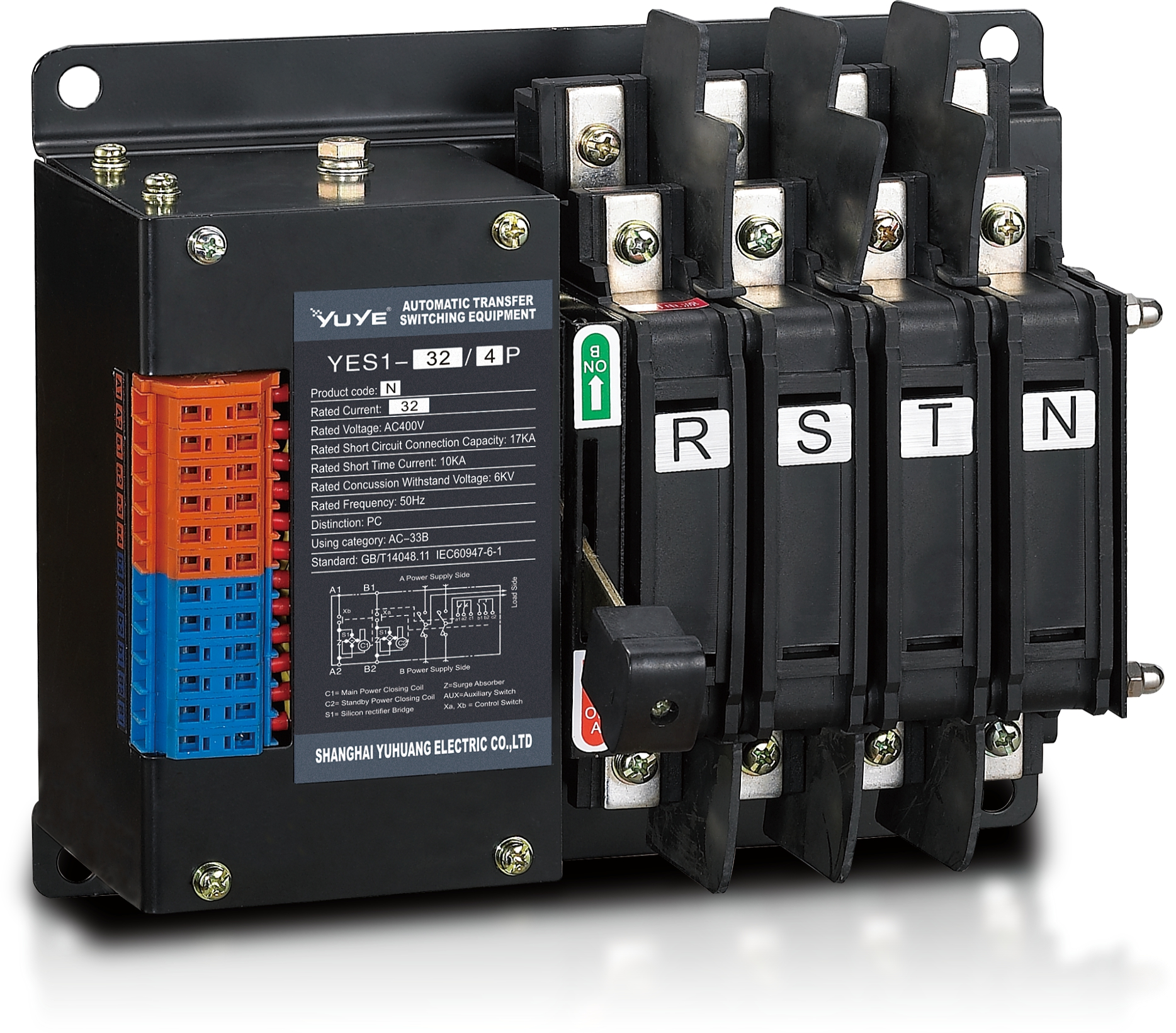 Solenoid-type ATS YES1-32~125N
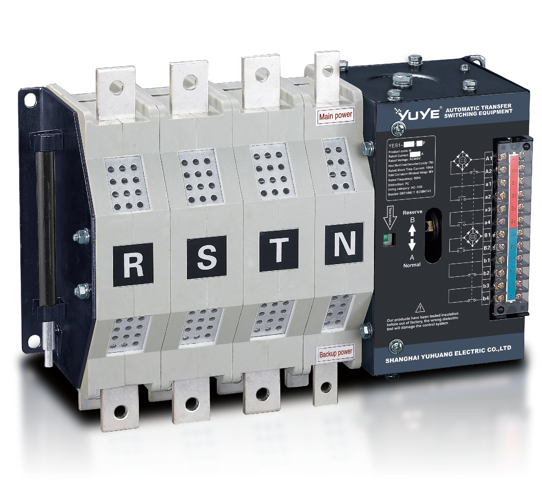 Solenoid-type ATS YES1-250~630N/NT
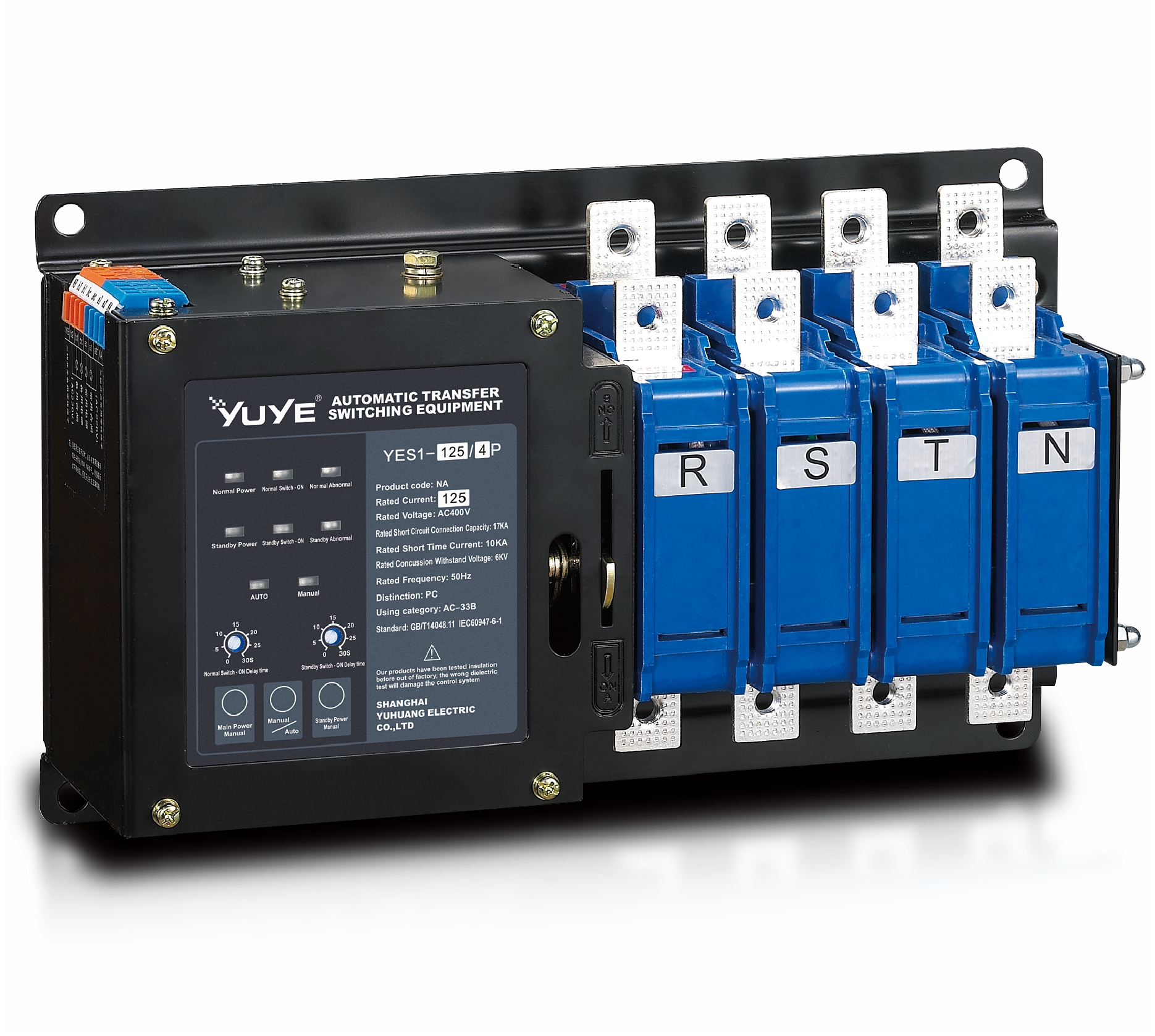 Solenoid-type ATS YES1-32~125NA
 Solenoid-type ATS YES1-63~630SN
 Solenoid-type ATS YES1-1250~4000SN
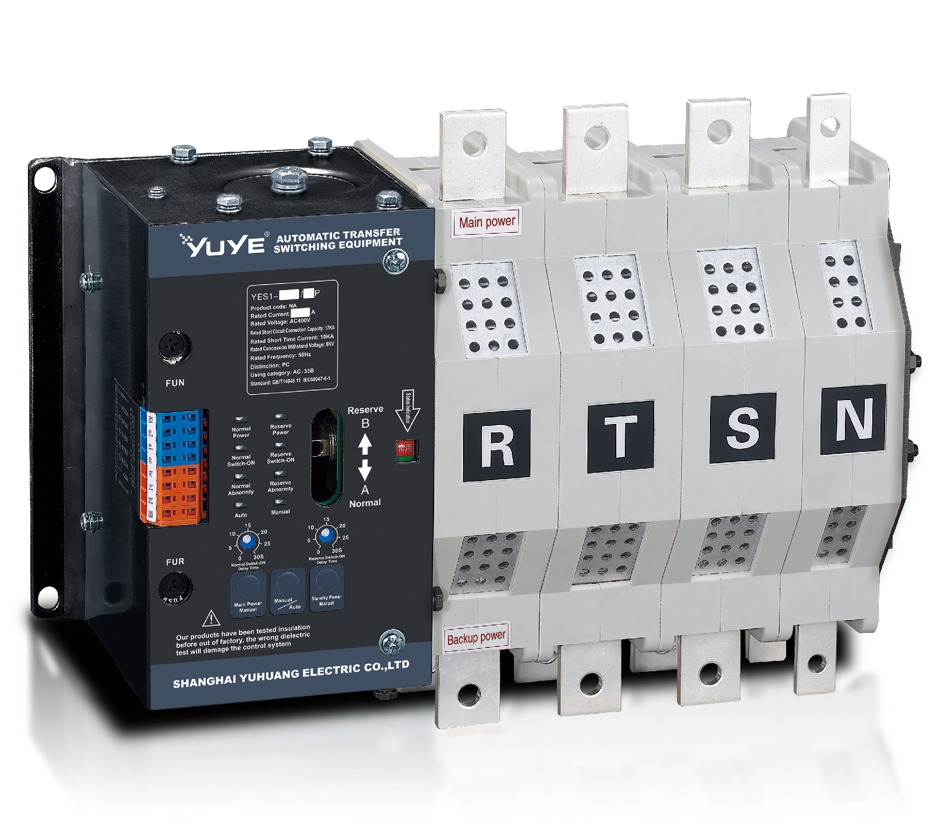 Solenoid-type ATS YES1-250~630NA/NAT
 Solenoid-type ATS YES1-63NJT
 PC ATS YES1-100~1600GN1/GN/GNF
 PC ATS YES1-2000~3200GN/GNF
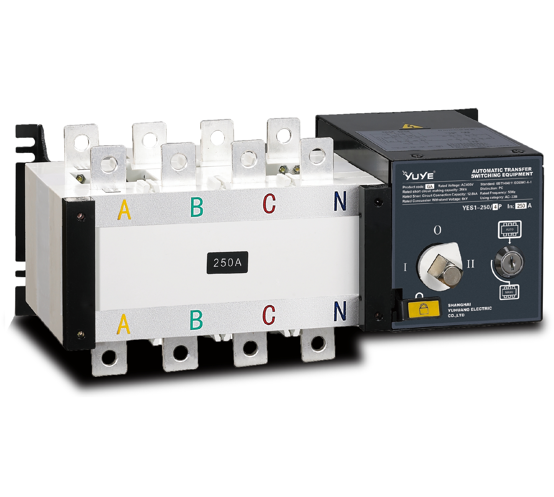 PC ATS YES1-100~3200GA1/GA
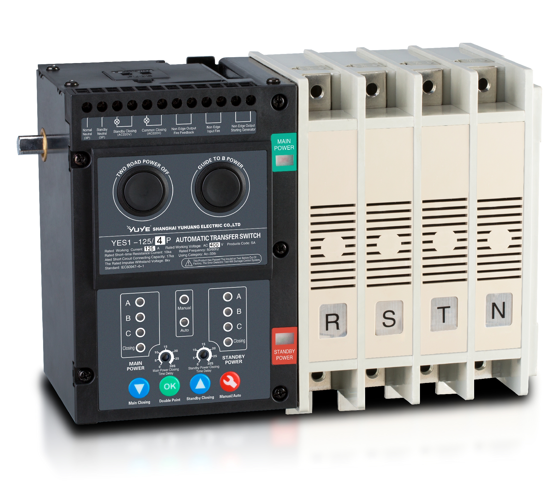 Solenoid-type ATS YES1-63~630SA
 Solenoid-type ATS YES1-63~630L/LA
 Solenoid-type ATS YES1-63~630LA3
 Solenoid-type ATS YES1-63MA
 PC ATS YES1-630~1600M
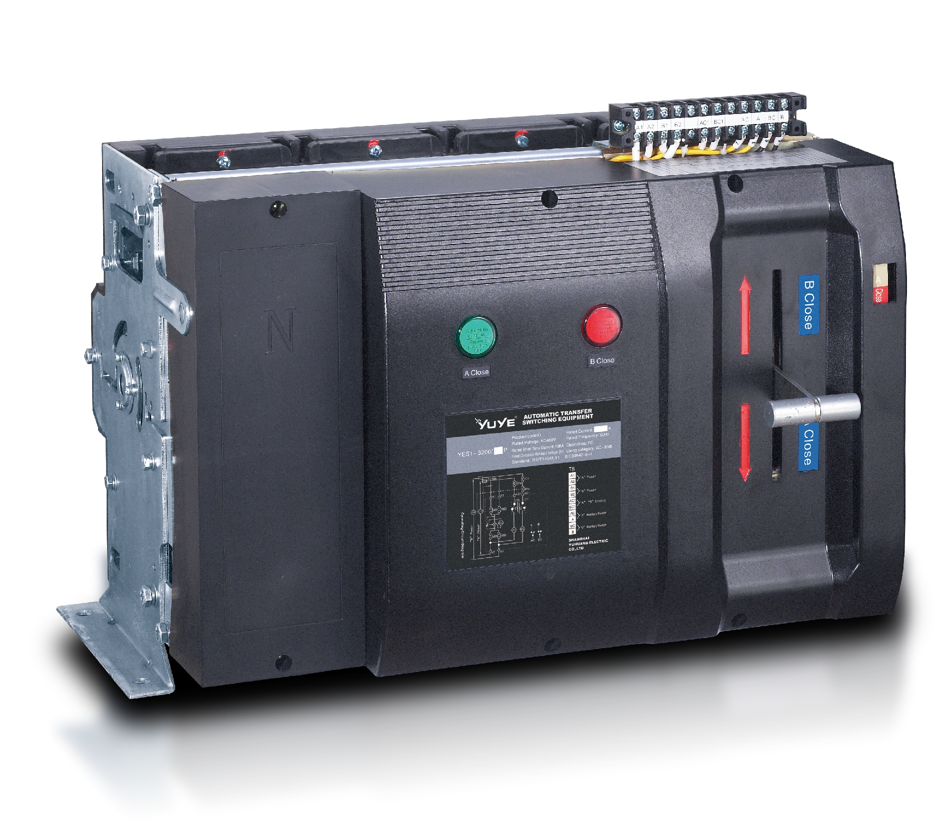 PC ATS YES1-3200Q
 Solenoid-type ATS YES1-4000~6300Q
 CB ATS YEQ1-63J
 CB ATS YEQ2Y-63
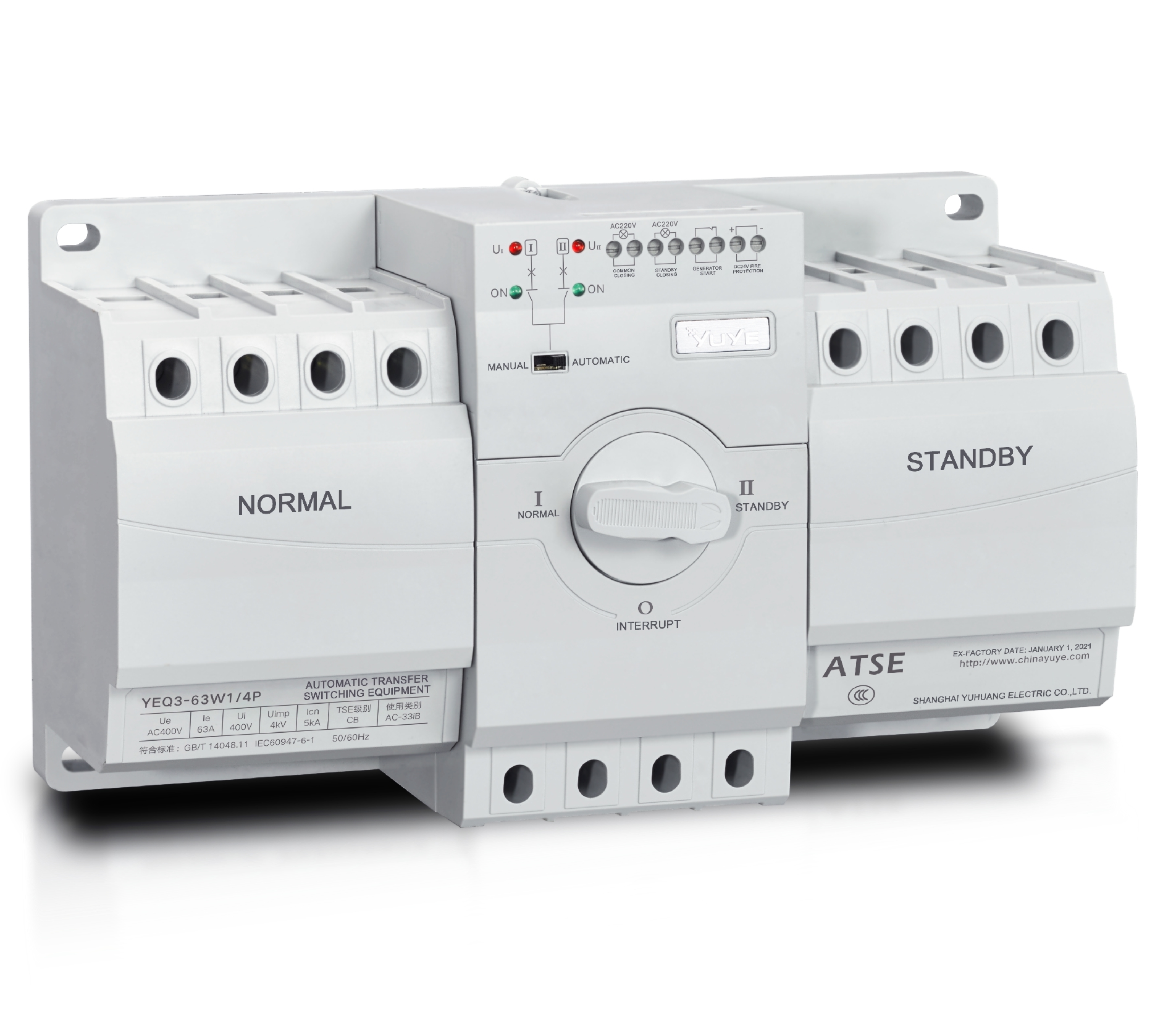 CB ATS YEQ3-63W1
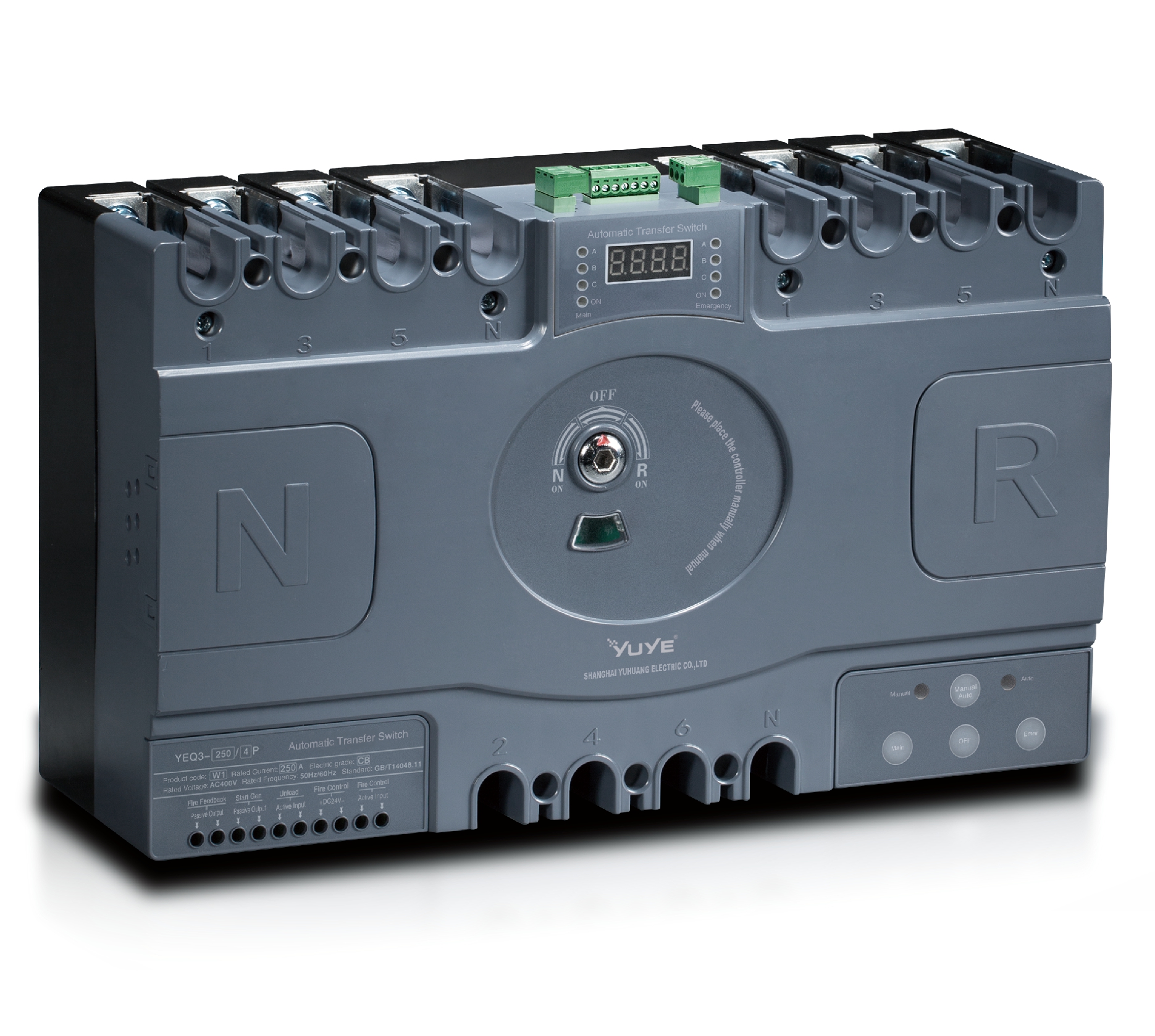 CB ATS YEQ3-125~630W1
 ATS controller Y-700
 ATS Controller Y-700N
 ATS Controller Y-701B
 ATS Controller Y-703N
 ATS Controller Y-800
 ATS Controller W2/W3 Series
 ATS switch Cabinet floor-to-ceiling
 ATS switch cabinet
 JXF-225A power Cbinet
 JXF-800A power Cbinet
 YEM3-125~800 Plastic Shell Type MCCB
 YEM3L-125~630 Leakage Type MCCB
 YEM3Z-125~800 Adjustable Type MCCB
 YEM1-63~1250 Plastic Shell Type MCCB
 YEM1E-100~800 Electronic Type MCCB
 YEM1L-100~630 Leakage Type MCCB
 Miniature circuit breaker YEMA2-6~100
 Miniature circuit breaker YEB1-3~63
 Miniature circuit breaker YEB1LE-3~63
 Miniature circuit breaker YEPN-3~32
 Miniature circuit breaker YEPNLE-3~32
 Miniature circuit breaker YENC-63~125
 Air Circuit Breaker YEW1-2000~6300
 Air Circuit Breaker YEW3-1600
 Load isolation switch YGL-63~3150
 Load Isolation Switch YGL2-63~3150
 Manual Changeover Switch YGL-100~630Z1A
 Manual Changeover Switch YGLZ1-100~3150
 YECPS2-45~125 LCD
 YECPS-45~125 Digital
 CNC Milling/Turning-OEM
 DC relay MDC-300M
 DC Isolation Switch YEGL3D-630
I. Introduction
High-current automatic transfer switches are core components of dual-power supply systems, undertaking the critical task of automatic power switching for heavy-load electrical equipment. The installation process of high-specification power switches is highly standardized, and construction quality directly determines the equipment’s operating stability and power supply safety. As a mainstream high-current switching device for industrial and commercial projects, ATS 630A has unique structural and installation requirements due to its large load capacity and mechanical switching structure. Non-standard on-site installation and irregular wiring will trigger equipment jamming, local overheating and switching failure, bringing hidden dangers to the entire power distribution system. This article elaborates on the mainstream installation forms, pre-construction preparations, standard operating procedures, wiring specifications and defect correction methods of ATS 630A, providing standardized technical guidance for on-site electrical construction and engineering acceptance.
II. Overview of Widely Used ATS 630A Installation Forms
In actual power distribution engineering, ATS 630A mainly adopts two mature and standardized installation modes: cabinet embedded installation and independent wall-mounted installation. The two methods have different structural fixing forms and design logic, adapting to diverse on-site construction environments and system layout requirements.
Cabinet embedded installation refers to fixing the equipment inside a standardized power distribution cabinet, featuring neat layout, good protection performance and convenient centralized management. This mode is widely used in centralized power distribution rooms of factories, commercial buildings and comprehensive projects, which require unified equipment management and standardized line arrangement.
Wall-mounted installation means directly fixing the equipment on the wall of the construction site with brackets. It has low space limitation and flexible construction, suitable for scattered field equipment, temporary power supply facilities and small-scale independent power distribution units. Construction teams can select the optimal installation mode according to project scale, site space and system layout planning.
III. Essential Tools and Preparations Before Installation
Adequate pre-installation preparation is the basis for standardized construction and safety operation. Before constructing ATS 630A, construction personnel need to prepare complete professional tools, including multimeter, level ruler, electric drill, fastening screwdrivers and wire stripping tools. Meanwhile, standard insulating gloves, insulating shoes and other safety protective equipment are required to comply with low-voltage electrical construction specifications.
On-site environment inspection is an indispensable pre-construction step. Workers need to clean the installation area to remove dust, debris and corrosive substances, measure the installation space size to ensure sufficient heat dissipation and operation space, and strictly confirm the complete power-off of main and standby power circuits to eliminate electric shock risks.
In addition, technical preparation should be completed in advance, including checking the integrity and parameter compliance of ATS 630A equipment, verifying the accuracy of construction wiring diagrams, and confirming the installation standards matching the project’s power distribution requirements, so as to avoid construction errors caused by unclear technical parameters.

IV. Detailed Operation of Wall-Mounted and Cabinet-Mounted ATS 630A
The wall-mounted installation process follows standardized fixed steps. First, complete positioning and marking according to the equipment size, and drill holes at the fixed position. After installing and fixing the mounting bracket firmly, place the equipment on the bracket, adjust the level ruler to ensure the equipment is horizontal and vertical, and finally tighten all fixing bolts to prevent loose deviation during long-term operation.
Cabinet embedded installation focuses on internal layout and overall matching. Firstly, fix the guide rail inside the power distribution cabinet according to the equipment specification, ensure the guide rail is flat and firm, then clamp the ATS 630A equipment on the guide rail accurately. Adjust the equipment position to keep uniform gaps with other cabinet components, realizing neat and standardized internal layout of the cabinet.
In the whole installation process, levelness and firmness are the core control points. Inclined installation will cause mechanical switching structure stress deviation, resulting in unsmooth switching action; insufficient fastening will lead to equipment vibration during operation, which will accelerate component wear and affect the long-term stable operation of the equipment.
V. Wiring Layout and Safety Norms During Installation
Standard wiring is the key to ensure the normal operation of ATS 630A. Construction personnel need to distinguish main power terminal, standby power terminal and load terminal strictly in accordance with the circuit diagram, and conduct wiring in a fixed sequence to avoid disorderly connection of lines.
In terms of wiring specifications, the wire diameter must match the 630A high-current load demand to prevent line overload and heating. All terminal wires need to be fully inserted and firmly fastened to avoid virtual connection and poor contact. Meanwhile, standardized grounding construction must be completed to release static electricity and prevent electric leakage accidents.
In the line layout process, cross wiring and chaotic winding are strictly prohibited. Power lines and control lines should be arranged separately and bound neatly, maintaining a safe spacing. This standard layout can effectively reduce electromagnetic interference between lines and avoid circuit short circuit and signal abnormality.
VI. Troubleshooting for Typical Installation Defects
In on-site construction, common installation defects include unlevel equipment fixation, loose bolt connection, non-standard wiring and reserved heat dissipation space insufficiency. These irregular operations are easy to be ignored in rapid construction, leaving long-term hidden dangers for equipment operation.
Improper installation will cause a series of adverse consequences. Unlevel installation affects mechanical switching accuracy, loose terminals lead to local overheating under high current, and insufficient heat dissipation space will cause continuous temperature rise of the equipment, accelerating aging of internal components and increasing failure probability.
For the above typical defects, targeted correction measures should be taken in time. Re-calibrate the equipment level and fix loose bolts again, reorganize irregular lines, and reserve sufficient ventilation and heat dissipation space around the equipment to ensure the equipment operates within a safe and standard environment.
VII. Conclusion
In summary, the installation quality of ATS 630A determines its operational safety and service life. Two mainstream installation modes have their own applicable scenarios, and standardized pre-construction preparation, professional mounting operation and standardized wiring norms are essential construction prerequisites.
Construction personnel should strictly abide by on-site installation standards, avoid common construction defects, and complete equipment installation and debugging in a standardized manner. Scientific and standard installation can effectively give full play to the performance advantages of ATS 630A, ensure the stable switching operation of dual-power systems, and provide reliable safety guarantees for various heavy-load power distribution projects.
References
1. National Electrical Construction Technical Specification. Installation Standard for Low-Voltage High-Current Switching Equipment, 2024.
2. Power Distribution Cabinet Installation and Layout Engineering Manual.
3. On-Site Safety Construction Guidelines for Automatic Transfer Switches.
4. Low-Voltage Electrical Equipment Wiring and Grounding Technical Specifications.
FAQ
Q1: What are the two standard installation methods for ATS 630A?
A1: It mainly includes cabinet embedded installation and independent wall-mounted installation. The two methods are applicable to centralized cabinet power distribution and scattered on-site power supply scenarios respectively.
Q2: Why is power-off confirmation required before ATS 630A installation?
A2: As a high-current electrical device, live construction will cause serious electric shock and short-circuit risks. Complete power-off is the primary safety principle for installation construction.
Q3: What is the core standard for ATS 630A installation construction?
A3: The core standards include firm and level fixation, standardized wiring matching, reasonable heat dissipation space reservation and compliant grounding installation.
Q4: What problems will insufficient heat dissipation space cause?
A4: It will lead to continuous heat accumulation during equipment operation, cause component overheating and aging, and even trigger switching faults and power safety accidents in severe cases.
Q5: Can the installation mode of ATS 630A be selected arbitrarily?
A5: No. It needs to be selected according to project layout, site space and power distribution management mode to ensure the best operating state and convenient later maintenance of the equipment.