 PC ATS YECT1-2000G
 PC ATS YES2-63~250GN1
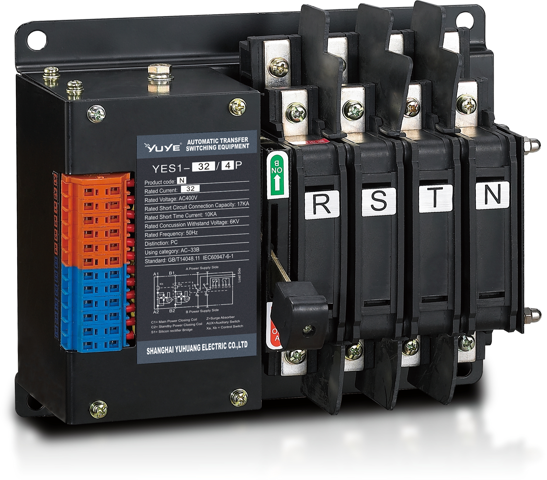 Solenoid-type ATS YES1-32~125N
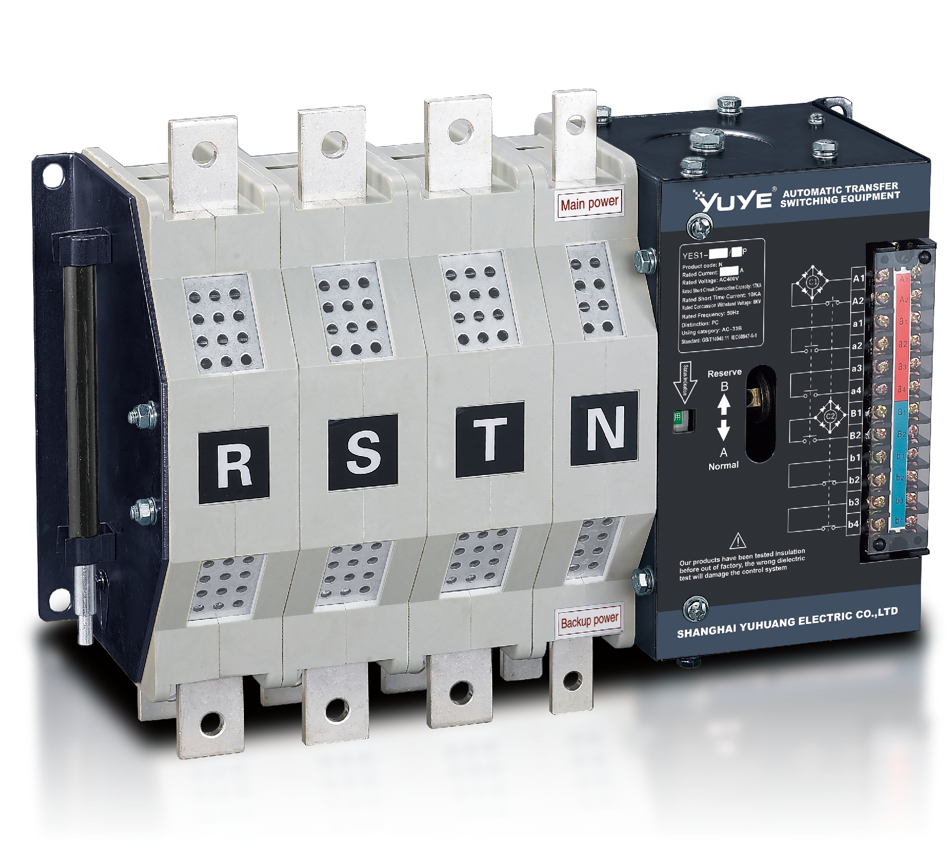 Solenoid-type ATS YES1-250~630N/NT
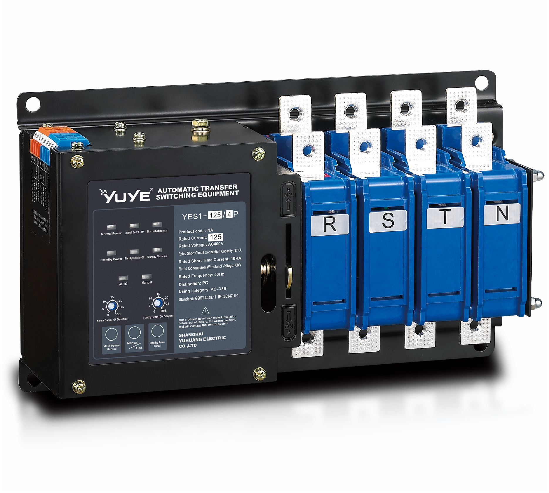 Solenoid-type ATS YES1-32~125NA
 Solenoid-type ATS YES1-63~630SN
 Solenoid-type ATS YES1-1250~4000SN
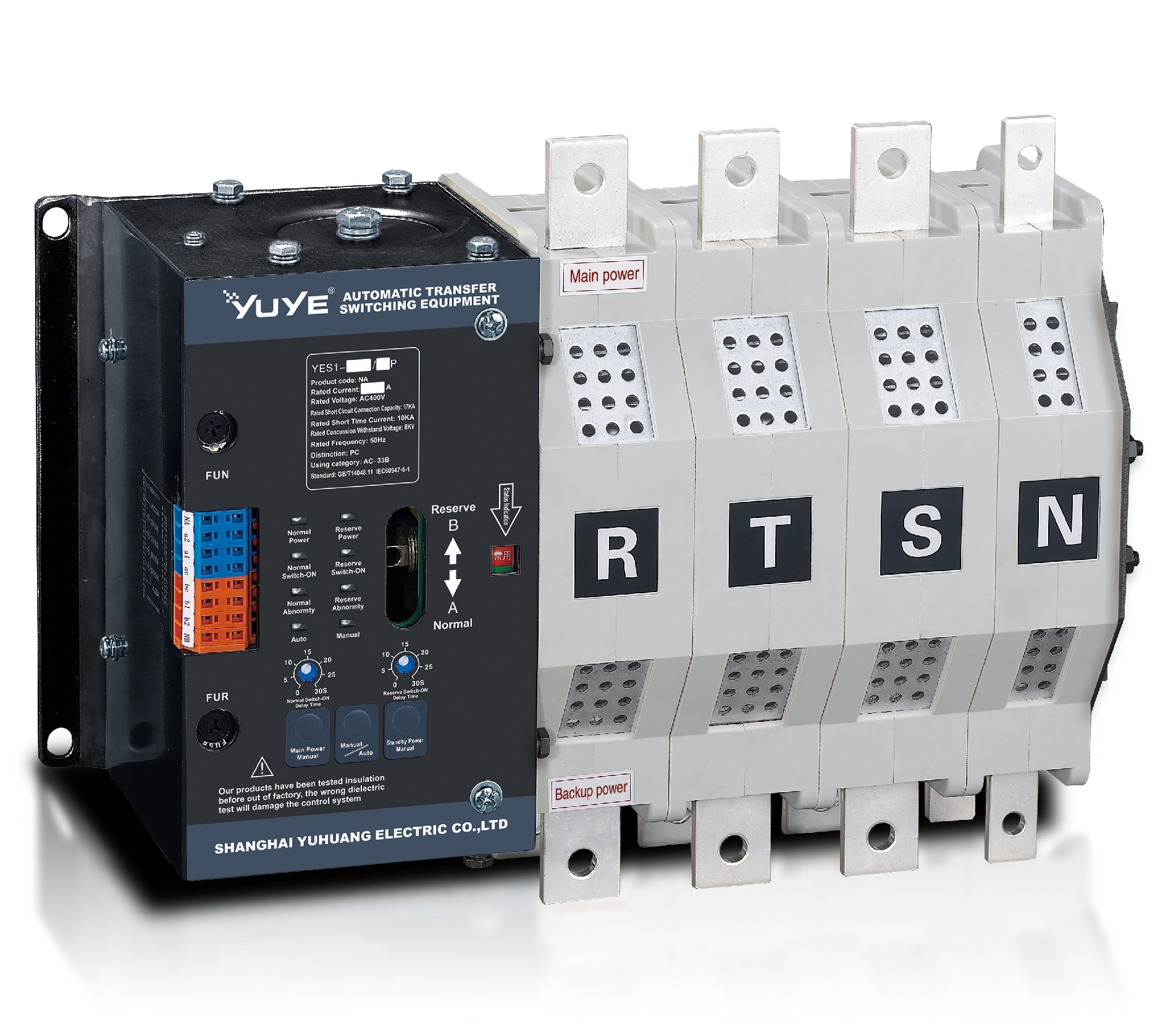 Solenoid-type ATS YES1-250~630NA/NAT
 Solenoid-type ATS YES1-63NJT
 PC ATS YES1-100~1600GN1/GN/GNF
 PC ATS YES1-2000~3200GN/GNF
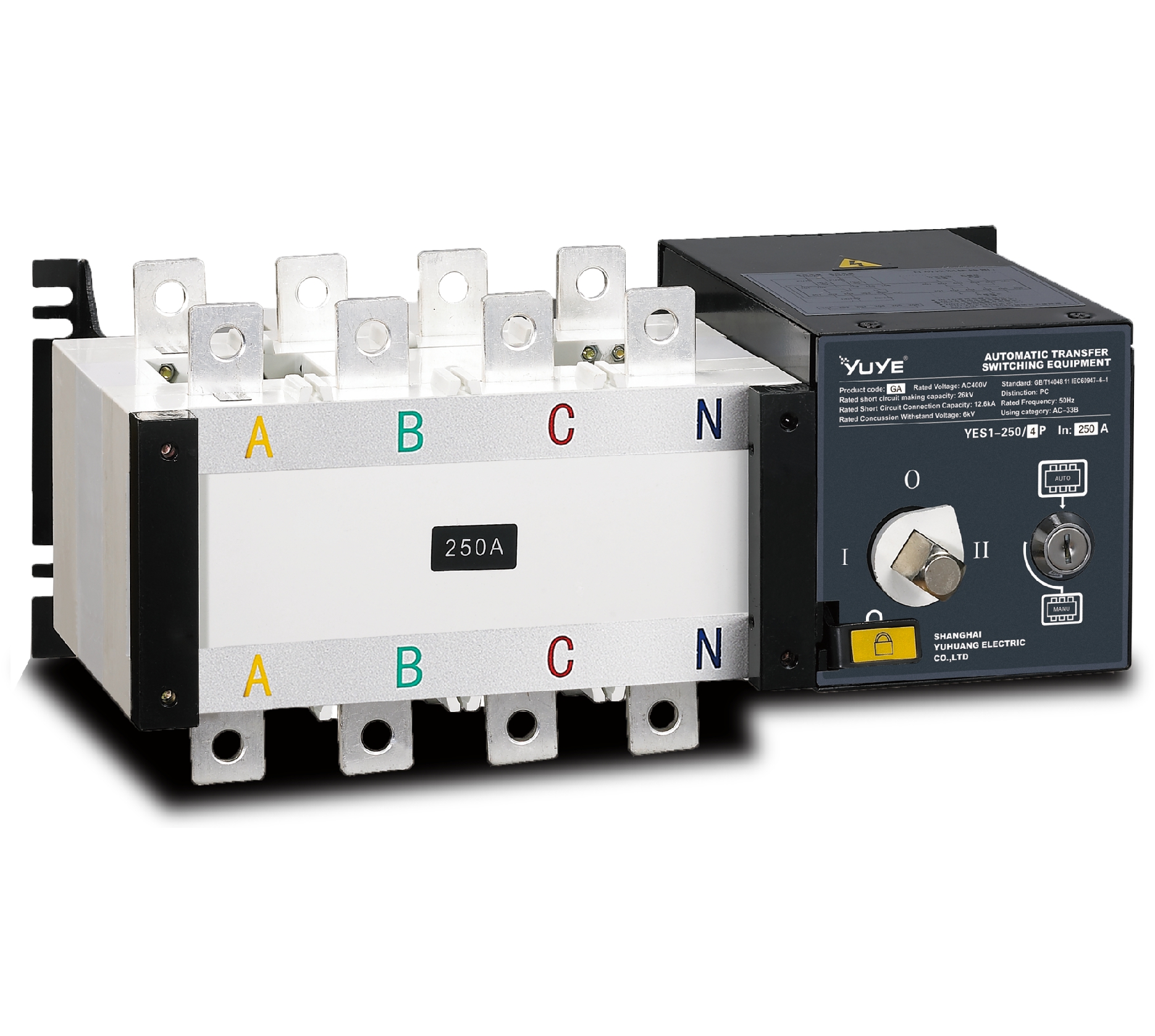 PC ATS YES1-100~3200GA1/GA
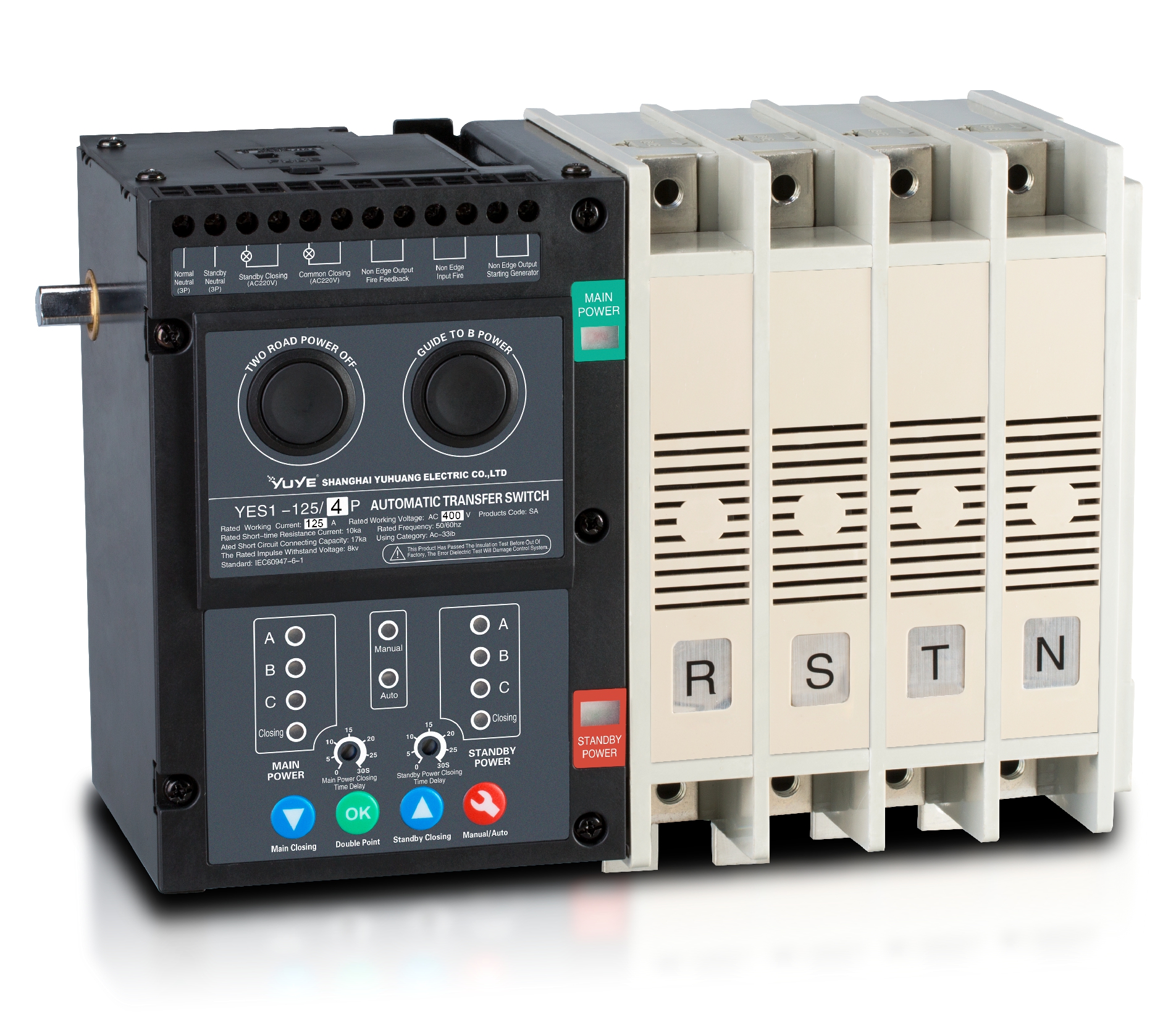 Solenoid-type ATS YES1-63~630SA
 Solenoid-type ATS YES1-63~630L/LA
 Solenoid-type ATS YES1-63~630LA3
 Solenoid-type ATS YES1-63MA
 PC ATS YES1-630~1600M
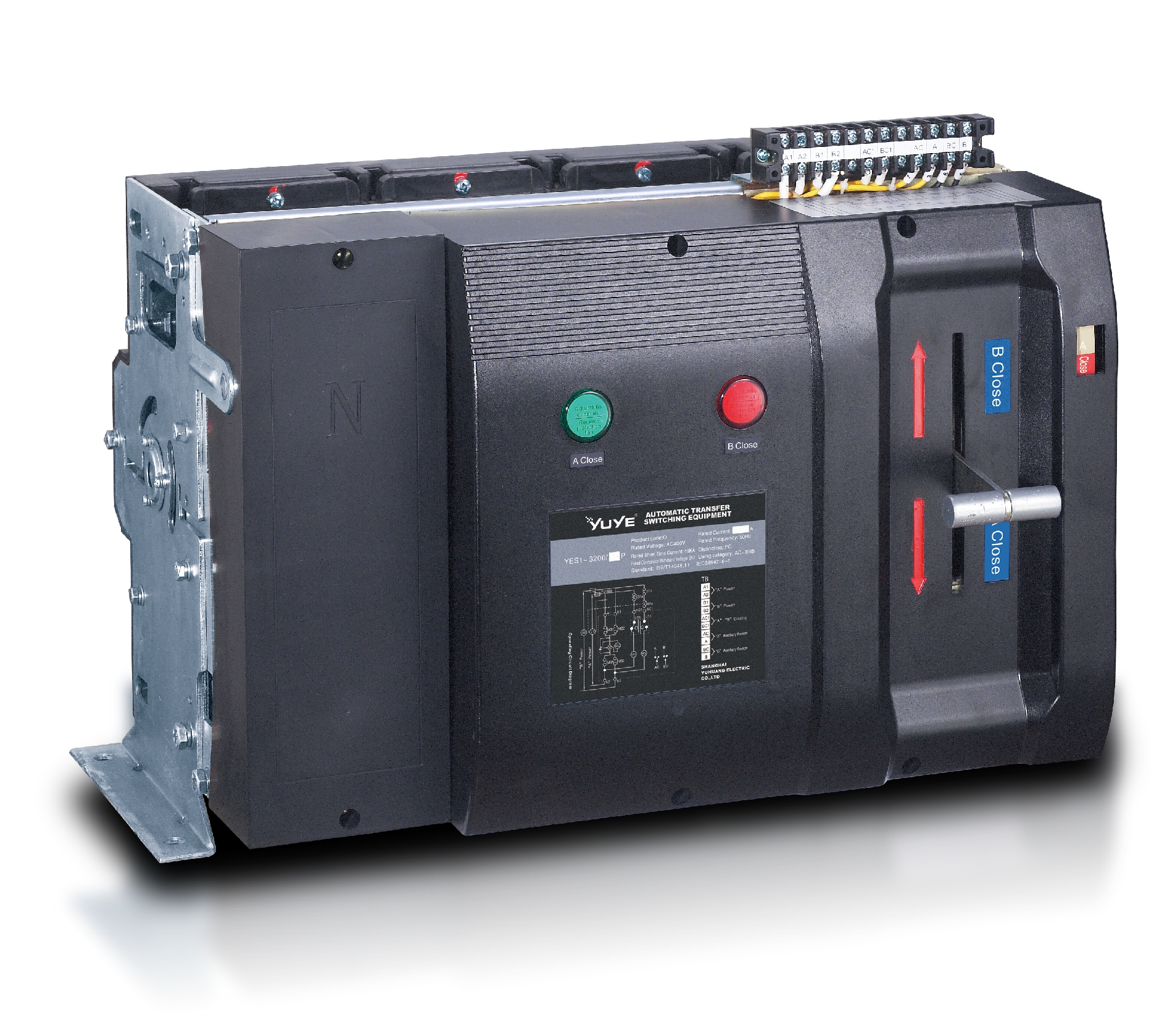 PC ATS YES1-3200Q
 Solenoid-type ATS YES1-4000~6300Q
 CB ATS YEQ1-63J
 CB ATS YEQ2Y-63
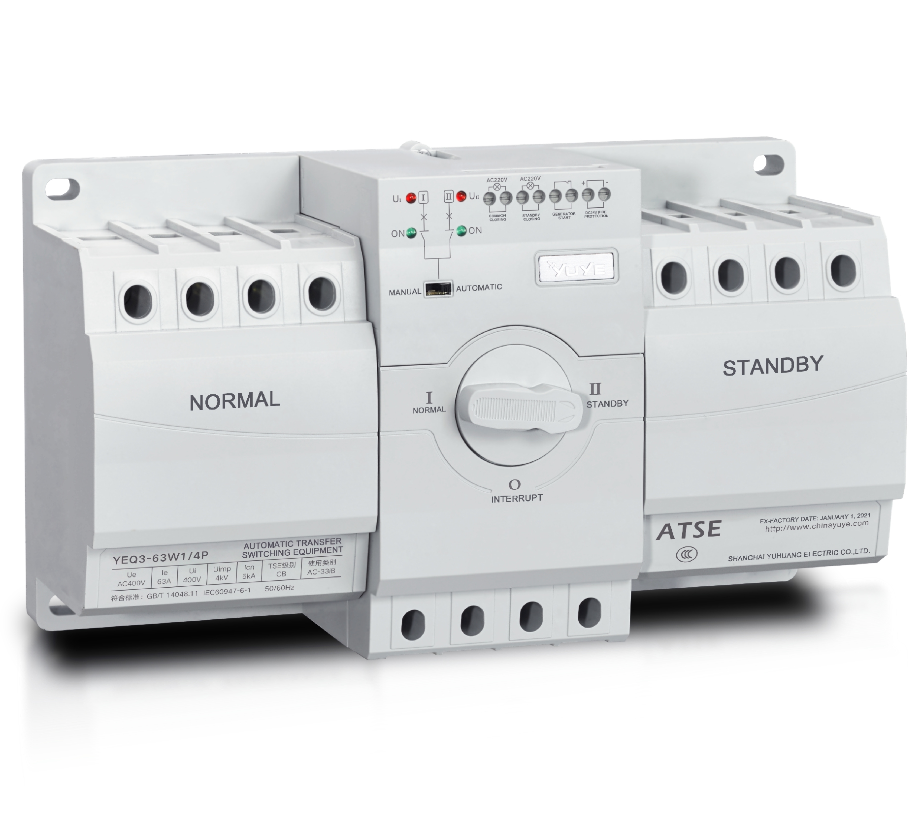 CB ATS YEQ3-63W1
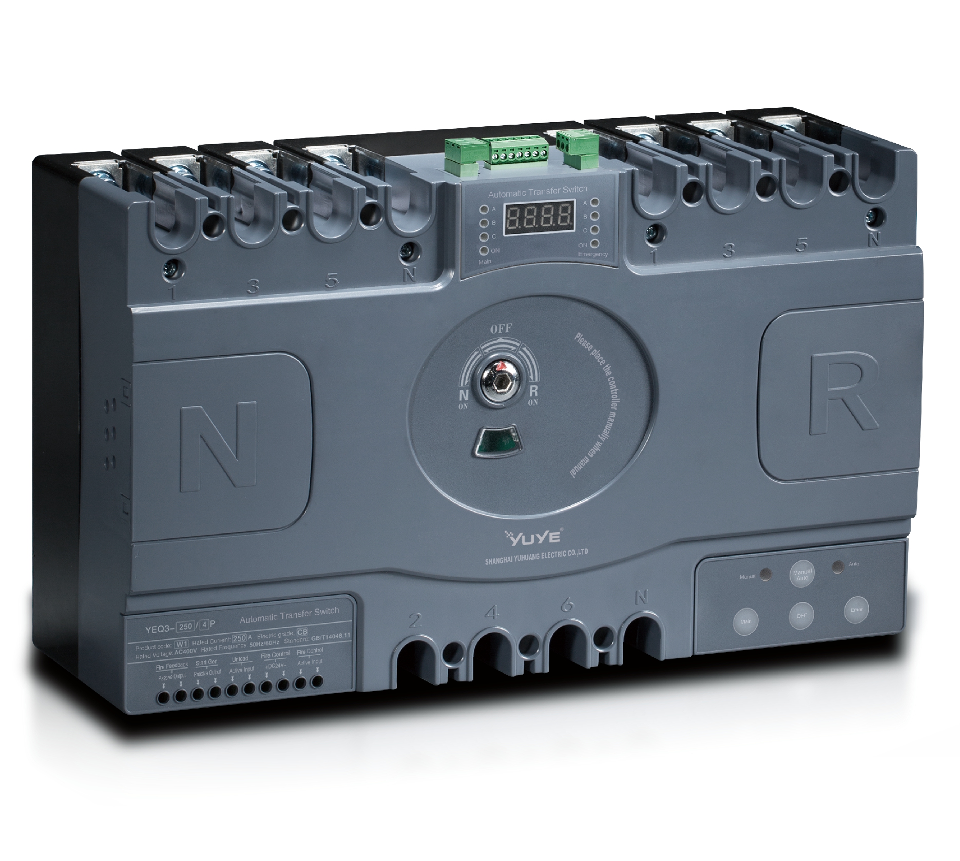 CB ATS YEQ3-125~630W1
 ATS controller Y-700
 ATS Controller Y-700N
 ATS Controller Y-701B
 ATS Controller Y-703N
 ATS Controller Y-800
 ATS Controller W2/W3 Series
 ATS switch Cabinet floor-to-ceiling
 ATS switch cabinet
 JXF-225A power Cbinet
 JXF-800A power Cbinet
 YEM3-125~800 Plastic Shell Type MCCB
 YEM3L-125~630 Leakage Type MCCB
 YEM3Z-125~800 Adjustable Type MCCB
 YEM1-63~1250 Plastic Shell Type MCCB
 YEM1E-100~800 Electronic Type MCCB
 YEM1L-100~630 Leakage Type MCCB
 Miniature circuit breaker YEMA2-6~100
 Miniature circuit breaker YEB1-3~63
 Miniature circuit breaker YEB1LE-3~63
 Miniature circuit breaker YEPN-3~32
 Miniature circuit breaker YEPNLE-3~32
 Miniature circuit breaker YENC-63~125
 Air Circuit Breaker YEW1-2000~6300
 Air Circuit Breaker YEW3-1600
 Load isolation switch YGL-63~3150
 Load Isolation Switch YGL2-63~3150
 Manual Changeover Switch YGL-100~630Z1A
 Manual Changeover Switch YGLZ1-100~3150
 YECPS2-45~125 LCD
 YECPS-45~125 Digital
 CNC Milling/Turning-OEM
 DC relay MDC-300M
 DC Isolation Switch YEGL3D-630
The automatic transfer switch (ATS) is a key device in dual power supply systems, mainly used to automatically switch between the main power supply and the backup power supply to ensure continuous power supply to critical loads. Standard and scientific installation not only relates to the safe operation of the equipment itself but also directly affects the stability of the entire power supply system and the convenience of later maintenance. This article provides a detailed explanation of the key points to note during the installation process, with special attention to Automatic Changeover Switch Wiring practices.
I. Environmental and Site Preparation Requirements Before Installation
Before installing the ATS, a comprehensive inspection of the installation environment must be carried out. The installation site should be kept dry, clean, and well ventilated. The environmental temperature and humidity should comply with the provisions of the equipment technical documents to avoid damage caused by high temperature, high humidity, or condensation.
The distribution room should have basic dust-proof and moisture-proof measures, with a flat floor and no water accumulation. Sufficient installation space and maintenance channels should be reserved to ensure convenient operation during later maintenance and component replacement. For places prone to vibration or electromagnetic interference, shock absorption and shielding measures should be taken, which also helps improve the safety of Automatic Changeover Switch Wiring.
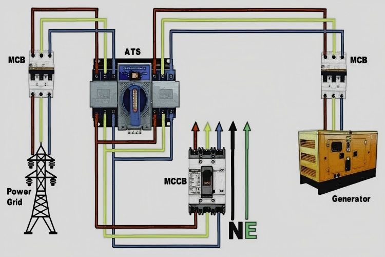
II. Wiring Specifications for Main Power Supply and Standby Power Supply
The wiring of the main power supply and backup power supply must be strictly carried out in accordance with design drawings and product manuals. The rated voltage, frequency, and capacity of the two power supplies should be consistent to ensure reliable switching performance.
Before wiring, it is essential to carefully check the phase sequence to ensure that the phase sequence of the main and backup power sources is consistent, preventing equipment malfunction or load damage. It is strictly forbidden to operate the two power sources in parallel, and mechanical and electrical interlock devices must be effective and reliable. Proper Automatic Changeover Switch Wiring ensures that both power sources remain electrically isolated and safely controlled.
Incoming and outgoing cables should be reasonably selected based on load capacity, and clear, durable line markings should be made to facilitate later maintenance and troubleshooting of Automatic Changeover Switch Wiring systems.
III. Key Points for Safety of Equipment Fixation and Installation Structures
The ATS equipment should be installed on a solid and flat foundation or cabinet to ensure uniform force distribution and prevent tilting or shaking. Installation brackets, rails, or cabinet structures should have sufficient mechanical strength to bear the equipment’s own weight and operational mechanical stress.
In areas prone to earthquakes or high-vibration environments, reinforcement measures should be taken in accordance with relevant seismic standards. The equipment casing should be reliably grounded and equipotential bonding should be properly implemented to ensure current can be safely discharged in case of faults, supporting the overall safety of Automatic Changeover Switch Wiring and system operation.
IV. Installation Precautions for Control Lines and Communication Interfaces
The control circuits should be laid separately from the main power cables to prevent electromagnetic interference from affecting control signals. A reasonable distance should be maintained between strong current and weak current lines, and when necessary, metal conduits or shielded cables should be used for protection.
ATS devices with communication functions (such as RS485 and Modbus interfaces) should be wired strictly in accordance with interface specifications, paying attention to positive and negative polarity and terminal resistor configuration. Communication cables should use shielded twisted-pair wires and be properly grounded to prevent signal interference and ensure stable Automatic Changeover Switch Wiring performance.
V. Key Points for Debugging and Safety Inspection After Installation Completion
Before the system is officially powered on, a comprehensive safety check should be conducted. First, perform an insulation resistance test to confirm that the insulation performance of the main circuit and control circuit meets the requirements.
Next, check whether the voltage, frequency, and phase sequences of the main and backup power supplies are normal. Test the automatic switching function by manually simulating a power failure to confirm correct switching logic and reliable operation. The reliability of manual/automatic switching should also be verified, ensuring that the Automatic Changeover Switch Wiring is functioning as designed.
Finally, check that safety warning signs and operation instruction labels are complete and clear to support standardized and safe operation.
Conclusion
Proper installation is the foundation for ensuring the long-term safe and stable operation of an ATS system. By strictly adhering to environmental preparation, wiring standards, equipment fixation, control circuit laying, and commissioning checks, the overall reliability and safety of the system can be significantly enhanced. Well-executed Automatic Changeover Switch Wiring plays a vital role in providing continuous and stable power for critical loads.