0%

Picking out a Dual Power Automatic Transfer Switch isn’t just about flipping through a catalog. It’s really about deciding how your vital equipment gets power when the main supply isn’t available. The right switch can smoothly shift a load over to a standby generator or another source, but choosing the wrong one could leave pumps, server racks, or production lines hanging in the air at the worst possible moment.

And let’s be honest, this risk isn’t just about theory. According to Uptime Institute’s 2024 Annual Outage Analysis, more than half of the organizations they surveyed—54%, to be exact—said their last big data center outage cost them over $100,000. Now, I’m not saying a transfer switch alone can prevent all outages, but it really underscores why careful power planning is such a big deal. Every little detail counts. When you’re shopping around, double-check system voltage, phases, rated current, number of poles, fault current capacity, and what your generator can handle. Don’t forget to think about transfer time, whether it’s a quick or gradual switch, control methods, enclosure ratings, and how easy it is to access for inspections.

Here’s the thing—application always comes before price. For example, a building with emergency lighting might need a different setup than a place with sensitive electronics or heavy motors. It’s a good idea to review everything — the one-line diagram, load schedules, generator specs — with a qualified electrician or an expert. Make sure the switch’s ratings line up with your installation and operational needs. Also, ask about testing procedures, alarms, and manual controls. No switch is a magic fix; a reliable system also depends on proper wiring, regular generator maintenance, and clear operating procedures. Often, those little details are the ones folks tend to overlook, but trust me, they’re worth giving a second thought to.”

How to Choose a Dualpower Automatic Transfer Switch?

Understand What a Dualpower Automatic Transfer Switch Does

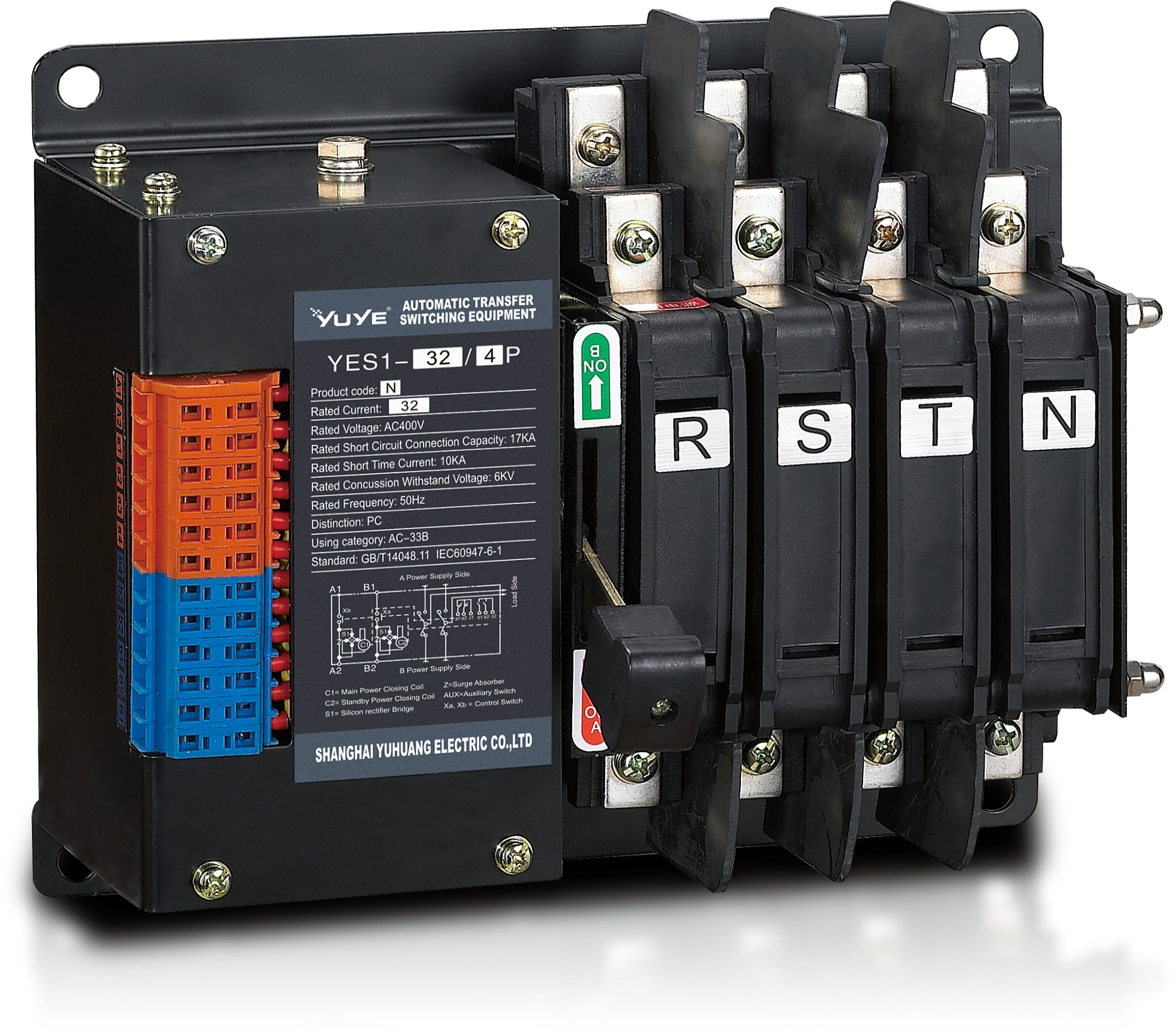
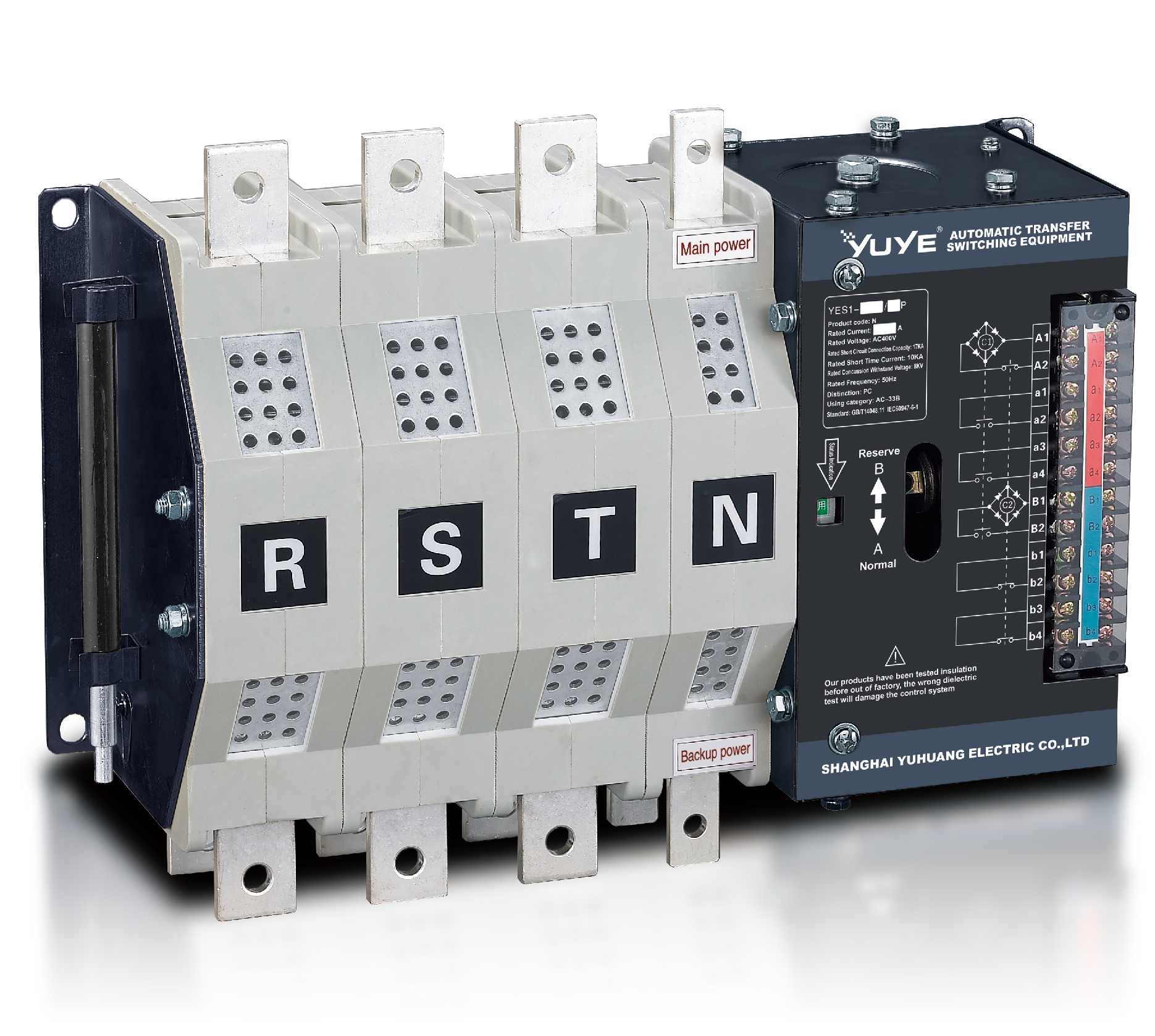
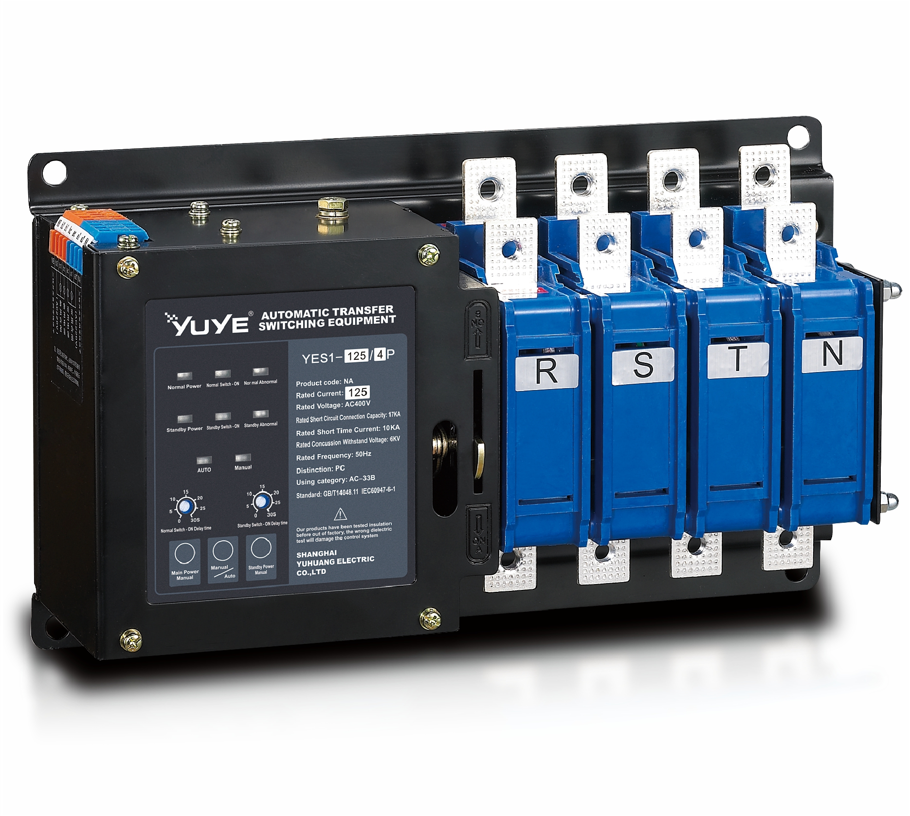
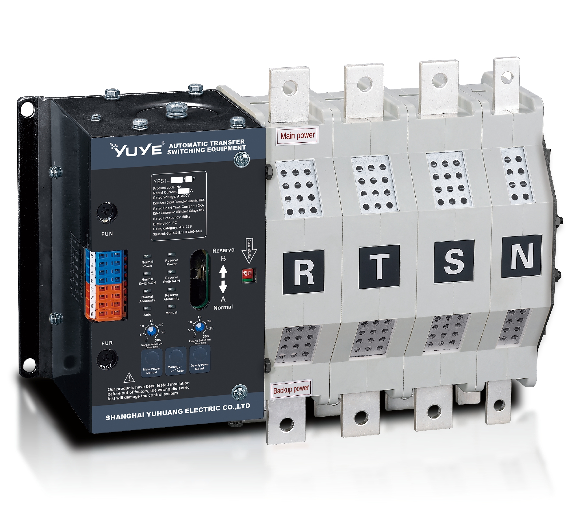
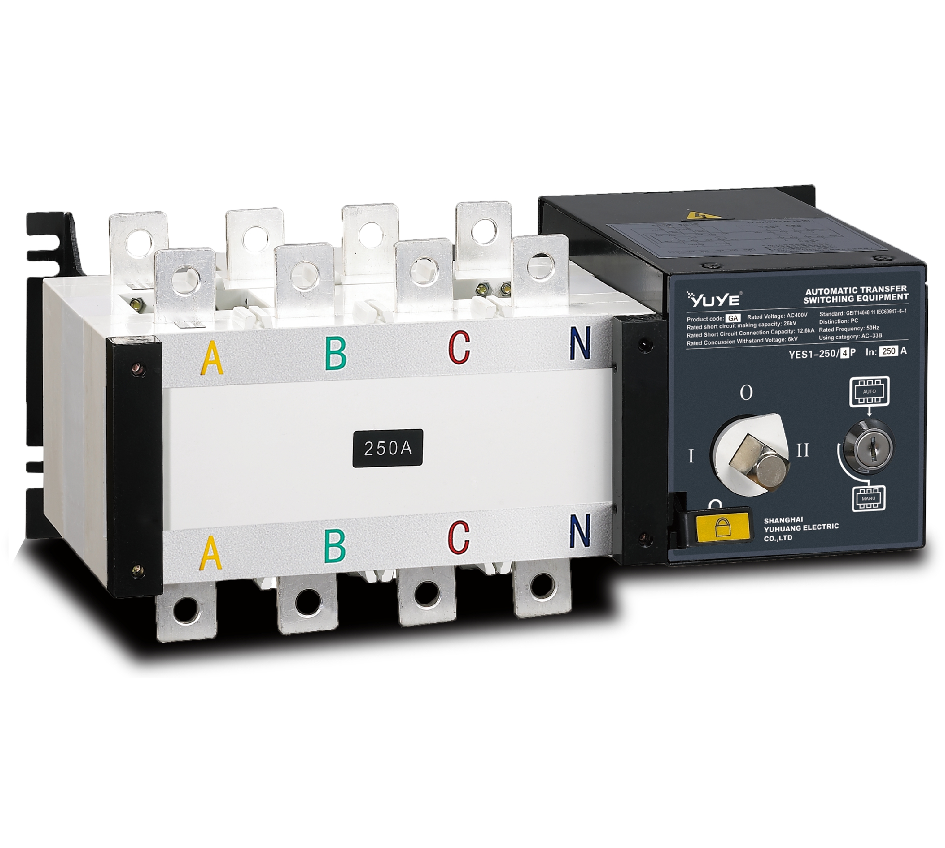
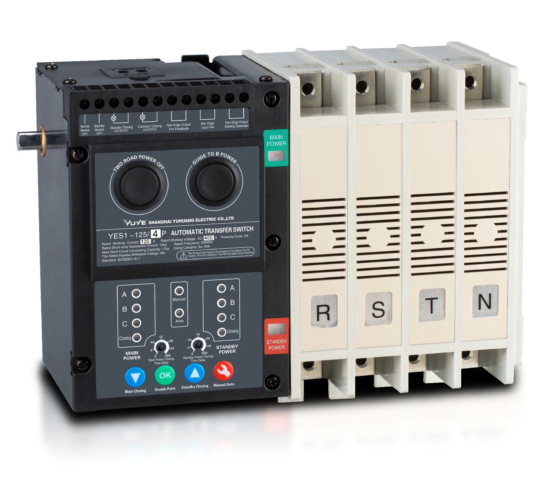
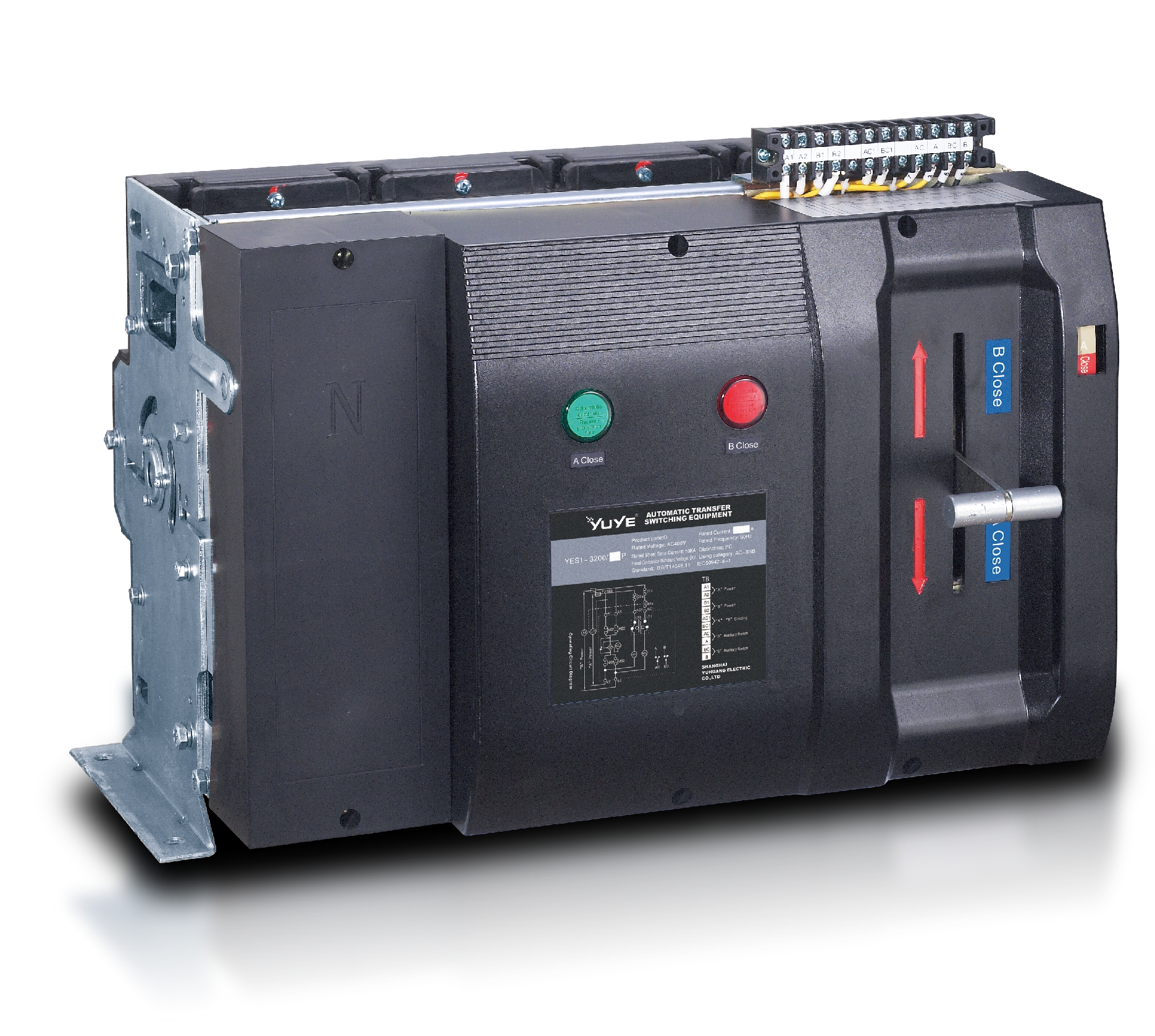
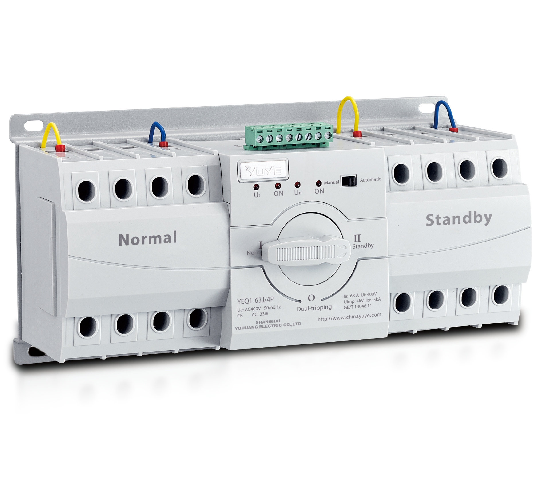
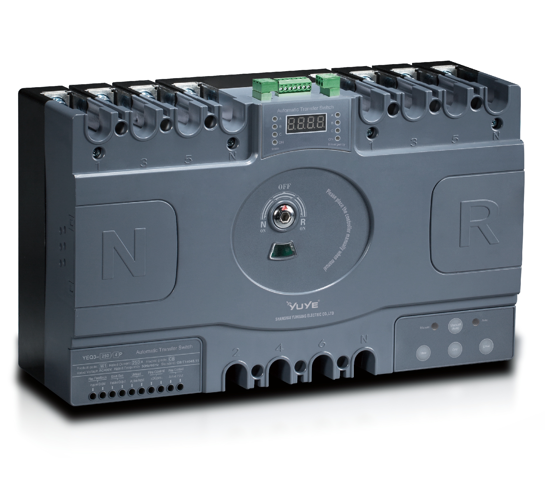
A dualpower automatic transfer switch connects a load to one of two available power sources, such as utility supply and a standby generator. It monitors the selected source for conditions like loss of voltage or an unacceptable voltage level. If that source fails, the switch can move the load to the alternate supply. That matters. The switch does not create electricity; it manages which source feeds the connected equipment.

Transfer is not always instant. Depending on the unit and system design, a generator may need time to start and stabilize before the load is transferred. When the preferred source returns, the switch may wait briefly before reconnecting, helping avoid a transfer during a momentary fluctuation. The exact sequence and timing vary, so check the equipment documentation rather than assuming every switch behaves the same way.

Choosing one starts with the load: note its voltage, phase, and current requirements, then confirm the switch is rated for them. Consider the available sources, expected transfer behavior, and whether the switch needs to support generator-start controls. A rating that looks adequate on paper can still be wrong for a specific installation. Have a qualified electrician verify the wiring, protection, and operating settings, and test the transfer under controlled conditions. Real systems can be less tidy than diagrams.

Identify the Power Sources and Transfer Requirements

Identify both sources before selecting a dualpower automatic transfer switch. Common pairs include utility and generator, or utility and a second independent supply. Record each source’s voltage, phase, frequency, grounding arrangement, and available capacity. Then compare those values with the switch and connected equipment ratings. A mismatch may look small on paper but can prevent safe, reliable transfer.

Define what must stay on. List critical loads, such as a freezer, network equipment, or a well pump, and note motor starting current, not just running watts. Decide which source has priority, how quickly transfer must occur, and whether the switch should pause while a generator stabilizes. The U.S. Energy Information Administration’s 2022 Electric Power Annual reports average customer interruptions of about 5.6 hours, including major events, and 2.5 hours excluding them. Those figures show why outage duration matters, but your site’s needs may differ. A load list can still miss a brief startup surge.

Tip: Photograph nameplates and map each circuit before specifying the switch. Confirm neutral and grounding requirements with a qualified electrical professional. Check transfer timing under real load, too; a neat spreadsheet is not a field test.

Calculate the Required Current and Load Capacity

To choose a Dualpower automatic transfer switch, calculate the highest current your backed-up loads may draw at the same time. For single-phase systems, use current = watts ÷ (voltage × power factor). For three-phase systems, use current = watts ÷ (1.732 × voltage × power factor). Use equipment nameplates where available, since power factor and rated voltage affect the result. Add the simultaneous loads, not every appliance in the building. Then compare the calculated current with the switch’s continuous current rating. Check both power sources and the required voltage, frequency, and number of poles. A larger kW figure alone does not guarantee a suitable switch.

Tips: List each load, its rated current, and whether it starts with a motor. Pumps, compressors, and air conditioners can draw much higher current briefly at startup. Check their starting data and the switch’s switching rating; don’t guess from running watts alone.

Leave an appropriate design margin according to the equipment instructions and applicable electrical requirements. Avoid adding an arbitrary percentage without checking the real load profile. Also confirm that the generator can support the selected loads, including starting surges. A switch can have enough current capacity while the generator still struggles. That part is easy to overlook. Before installation, have a qualified electrician verify the calculations, protection, and neutral arrangement. Real loads may behave differently from a tidy spreadsheet.

Match Voltage, Phase, Poles, and Switching Type

Choosing a dual-power automatic transfer switch starts with the load’s actual supply: confirm nominal voltage, frequency, and whether the system is single- or three-phase. A 208-volt, three-phase panel cannot be matched by voltage alone; phase and wiring must also align. Check the switch’s continuous-current rating and available fault-current rating against the installation, not just the generator nameplate. Small details matter.

Pole count depends on the system’s grounding and neutral arrangement. A three-pole switch usually leaves the neutral connected, while a four-pole design switches it; have a qualified electrical professional confirm which arrangement suits the site. Check the neutral. Then choose the switching type: open transition briefly interrupts power, while closed transition overlaps sources for a smoother transfer and requires source synchronization and utility coordination. Delayed transition can help with loads that need time to shed residual voltage. Uptime Institute’s 2024 Annual Outage Analysis reported that 54% of respondents said their most recent significant outage cost more than $100,000. That figure is a reminder to treat compatibility checks as reliability work, not paperwork. I would verify the actual wiring diagram before ordering; catalog descriptions can leave important details unclear.

Compare Transfer Modes and Control Features

Compare Transfer Modes and Control Features

A dual-power automatic transfer switch should match the way your loads respond to an interruption. With open transition, the switch disconnects one source before connecting the other, creating a short break. This often suits general building loads. Closed transition briefly overlaps sources, so they must be synchronized and the installation designed for paralleling. Delayed transition adds a pause between sources, which can help with motor loads that need time to shed residual voltage. Small details matter.

Control settings shape how reliably that transfer happens. Check adjustable voltage and frequency limits, transfer delays, return-to-normal settings, alarms, and event logging. For example, a generator may need several seconds to stabilize before accepting a load. A test mode can verify operation without forcing a real outage. Remote monitoring is useful, but only if someone reviews its alerts. I would not choose by feature count alone; settings that are difficult to configure can create their own risks.

The stakes are real. Uptime Institute’s 2024 Annual Outage Analysis reported that 54% of surveyed operators said their most recent significant outage cost more than $100,000. That figure does not mean every outage can be prevented by an ATS. It does show why transfer behavior deserves careful review. Match the switch’s rated current and fault withstand capability to the installation, then confirm the control sequence with the equipment supplier and a qualified engineer. Catalog comparisons can miss the site-specific part.

Check Safety Standards and Installation Requirements

Before buying a dual-power automatic transfer switch, check that its certification matches the installation. UL 1008 covers transfer-switch equipment in North America; IEC 60947-6-1 covers transfer switching equipment internationally. Confirm the switch’s voltage, current, pole count, and short-circuit withstand rating against the panel and both power sources. A generator’s output may differ from the utility supply. Neutral switching and grounding arrangements also need review, not guesswork.

Installation rules are just as important as the nameplate. NFPA’s Home Electrical Fires report estimated an annual average of 24,200 home electrical fires in the United States from 2015 to 2019, with $1.2 billion in direct property damage. The report does not attribute these fires specifically to transfer switches, but it shows why careful electrical work matters. Have a qualified electrician verify available fault current, overcurrent protection, conductor sizing, enclosure location, and required clearances against local codes and the equipment instructions.

Test the full transfer sequence under controlled conditions: loss of the normal source, generator start, load transfer, and safe retransfer. Keep the test record. A checklist can still miss a detail, especially when older panels are involved. That deserves a second look.

Verify Compatibility with the Backup Power System

A dual-power automatic transfer switch must match the backup system’s electrical characteristics, not just its advertised capacity. Check the system voltage, phase, frequency, and rated current against the switch nameplate and installation documents. A mismatch can cause nuisance trips, overheating, or unreliable transfer. For example, a single-phase generator cannot properly serve a load arrangement designed for three-phase supply. Small details matter.

Also confirm how the backup source starts and how the switch handles neutral and grounding. Some generators provide a remote start signal; others require a different control arrangement. Neutral switching requirements depend on the system design, so do not assume every installation uses the same configuration. Check the manuals for both the switch and the generator, then have a qualified electrician verify the wiring and protection settings. If the backup source is an inverter, confirm its output waveform and overload capability, especially when pumps or compressors start. Their brief inrush current can exceed normal running demand. I have seen capacity look adequate on paper, yet startup behavior tell a different story. That deserves a closer check.

How to Choose a Dualpower Automatic Transfer Switch? — Verify Compatibility with the Backup Power System
Compatibility Check Example System Details What the ATS Must Match Verification Method Important Note
Voltage and phase 230 V single-phase, or 400/230 V three-phase, 50 Hz Rated operating voltage and phase arrangement must match both the normal and backup supplies. Compare the supply nameplates and wiring diagrams with the ATS voltage and phase specifications. Do not assume a three-phase ATS is suitable for a single-phase installation, or vice versa.
Frequency 50 Hz or 60 Hz, as applicable to the installation The ATS sensing and operating range must support the frequency of both sources. Check the ATS frequency rating and confirm the generator or inverter output frequency under load. An out-of-range backup frequency may prevent transfer or cause connected equipment to operate incorrectly.
Number of poles and neutral switching Two-pole switching for many single-phase systems; four-pole switching may be used for three-phase systems with a switched neutral. Pole configuration must suit the earthing arrangement and whether the neutral needs to be switched. Have a qualified electrician review the supply earthing arrangement, generator neutral bond, and local electrical rules. Neutral switching requirements vary by system design and jurisdiction; pole count alone does not determine suitability.
Continuous current rating Example: a 63 A ATS for a circuit whose calculated maximum current does not exceed its permitted rating. The ATS current rating must be suitable for the load, conductors, protective devices, and installation conditions. Calculate the design load and check the ATS rating, ambient-temperature limits, and any required derating. Do not select an ATS from the generator’s headline power rating alone; check current on each phase.
Backup source capacity Generator or inverter sized for the expected running load and motor-starting demand. The backup source must support the transferred load without unacceptable voltage or frequency drop. Include starting currents from motors, pumps, compressors, and other large loads in the source-capacity assessment. A generator’s standby or peak rating is not necessarily its continuous usable output.
Inverter or battery-system compatibility Backup inverter with a defined AC output voltage, frequency, neutral arrangement, and overload capability. The inverter must permit connection through an external transfer device and support the switching arrangement. Check the inverter documentation for external transfer-switch requirements, output limits, and neutral/earth instructions. The ATS must prevent unintended paralleling of independent sources unless the complete system is specifically designed for parallel operation.
Transfer behavior and timing Open-transition transfer, where one source is disconnected before the other is connected. The ATS transfer mode and timing must suit the load’s tolerance for a brief interruption. Review the specified detection, delay, and transfer times, then compare them with the load requirements. Most open-transition transfers interrupt power briefly. Loads needing uninterrupted power may require a UPS.
Short-circuit withstand and protection Available fault current determined at the ATS installation point. The ATS short-circuit rating and any required upstream protective device combination must be adequate. Use a fault-current calculation and verify the ATS rating against the applicable protection-device data. The installation’s prospective fault current cannot be inferred from the ATS current rating.
Control power and generator start interface Generator with a two-wire remote-start input, or an inverter system with a compatible enable or status interface. Control voltage, contact type, terminal arrangement, and start/stop logic must be compatible. Compare the ATS control schematic with the backup source’s control-interface documentation. Do not apply a control voltage to a dry-contact input unless the equipment instructions explicitly allow it.
Load type and switching duty Mixed loads, potentially including lighting, electronic equipment, and inductive motor loads. The ATS must be rated for the load category and switching duty expected in the installation. Identify motor and transformer loads and check the applicable utilization or load-category ratings. Large inrush currents may require a higher-rated switching device or load sequencing.
Installation environment Indoor panel, outdoor enclosure, or equipment room with a specified ambient temperature. Enclosure protection, temperature range, clearances, and mounting method must suit the location. Check the enclosure rating and installation instructions against exposure to dust, moisture, heat, and ventilation limits. An ATS rating may require derating at elevated ambient temperatures or when installed in a confined enclosure.

How to Select and Apply the YEGL3D-630 DC Isolation Switch for Reliable Power Systems

As renewable installations expand, dependable DC isolation becomes increasingly important. IRENA’s *Renewable Capacity Statistics 2024* reports that global renewable power capacity reached 3,870 GW by the end of 2023, an increase of 13.9% in one year. When selecting a YEGL3D-630, first confirm that the system’s maximum DC voltage is within its 1,000 V or 1,500 V rating, then choose a rated current from 80 A to 630 A to suit the circuit’s design load and operating conditions. Its two-pole configuration supports isolation of both DC conductors; the 2,000 V insulation rating and 12 kV impulse withstand rating are also key parameters to check against the installation design.

For reliable operation, account for enclosure temperature, conductor sizing, and expected switching duty rather than selecting by nominal current alone. The switch’s electrical life is 500 cycles for frame currents up to 315 A and 400 cycles above 315 A; mechanical life is rated at 10,000 forward rotations or 3,000 side rotations. Confirm the required operating orientation and maintenance plan before installation, and verify that the selected configuration meets GB/T 14048.3 and IEC 60947-3 requirements. This approach helps match the isolation device to the system’s voltage, current, and service demands.

FAQS

What does an automatic transfer switch do?

It connects a load to one of two power sources. If the selected source fails, it can transfer the load to the alternate source. It manages power; it does not generate electricity.

Does power transfer happen instantly?

Not always. A generator may need time to start and stabilize. The switch may also wait briefly before returning to the preferred source. Timing depends on the equipment and system.

How do I estimate the switch’s current requirement?

Add the current of loads that may run at the same time. For single-phase systems, use watts ÷ (voltage × power factor). For three-phase systems, use watts ÷ (1.732 × voltage × power factor). Check equipment nameplates where possible.

Is running current enough when selecting a switch?

No. Pumps, compressors, and air conditioners may draw much more current during startup. Check their starting data and the switch’s switching rating. Don’t guess from running watts alone.

Which electrical details should match the installation?

Confirm voltage, frequency, phase, current rating, and available fault-current rating. A three-phase panel needs a compatible switch, even when the voltage seems to match. Small details matter.

How do I choose the number of poles?

Pole count depends on the system’s grounding and neutral arrangement. A three-pole switch usually leaves the neutral connected; a four-pole switch switches it. Check the neutral. Have a qualified electrician confirm the correct arrangement.

What is the difference between open and closed transition?

Open transition briefly interrupts power. Closed transition overlaps sources for a smoother transfer, but requires synchronization and utility coordination. Delayed transition can help with certain loads. Verify the wiring diagram before ordering.

Can a higher-capacity switch solve every backup-power problem?

No. The generator must also support the selected loads and their startup surges. A switch may have enough current capacity while the generator struggles. I may be overlooking a site-specific detail, so have an electrician verify the calculations and test the system under controlled conditions.

Conclusion

Choosing a Dualpower Automatic Transfer Switch begins with understanding its role: it monitors the normal power supply and transfers a connected load to a backup source when needed. First, identify both power sources, the equipment being protected, and how quickly power must be restored. Then calculate the expected current and total load capacity, allowing for operating conditions and any starting demands from connected equipment.

Next, match the switch to the system’s voltage, phase, number of poles, and preferred switching type. Compare available transfer modes and control features to find an arrangement suited to the application. Before installation, check relevant safety standards, site requirements, and the need for qualified installation. Finally, confirm that the switch works with the backup power system, including its electrical characteristics and control signals, so the complete setup can transfer power reliably and safely.

Blog Tags:

Noah

Noah

Noah is a dedicated marketing professional at One Two Three Electric Co., Ltd., a distinguished manufacturer renowned for its high standards in the development and production of molded case circuit breakers and air circuit breakers. With a profound expertise in electrical solutions, Noah......
Previous How to Choose an Automatic Transfer Switch 220V?
Click For Inquiry