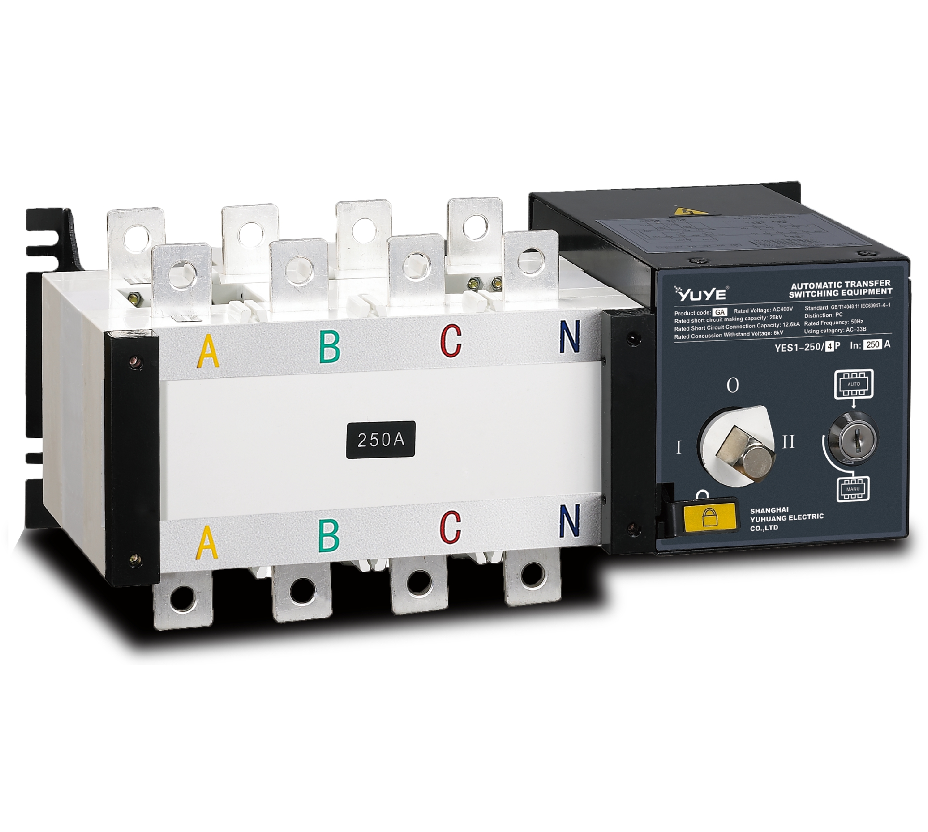
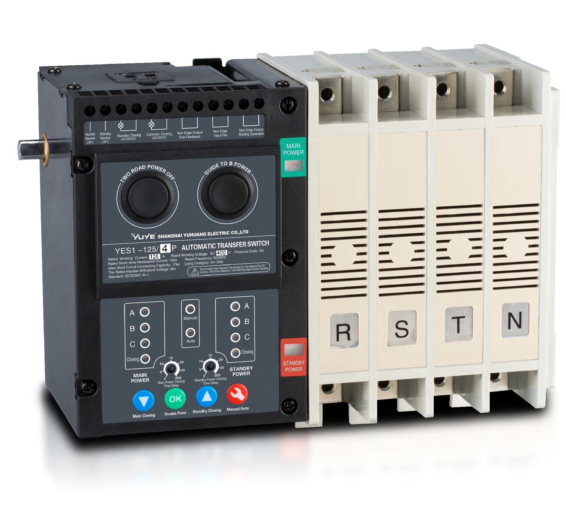
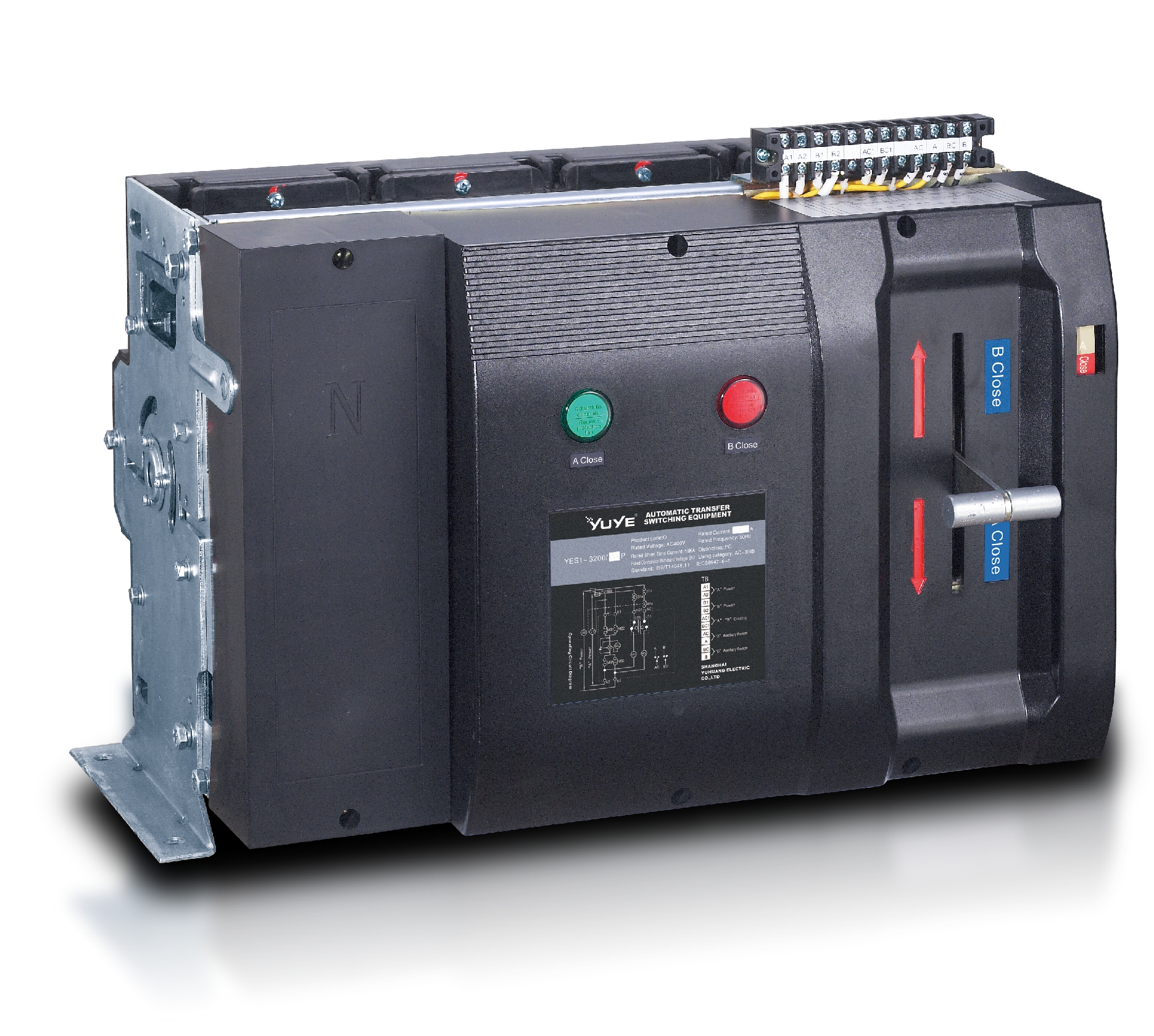
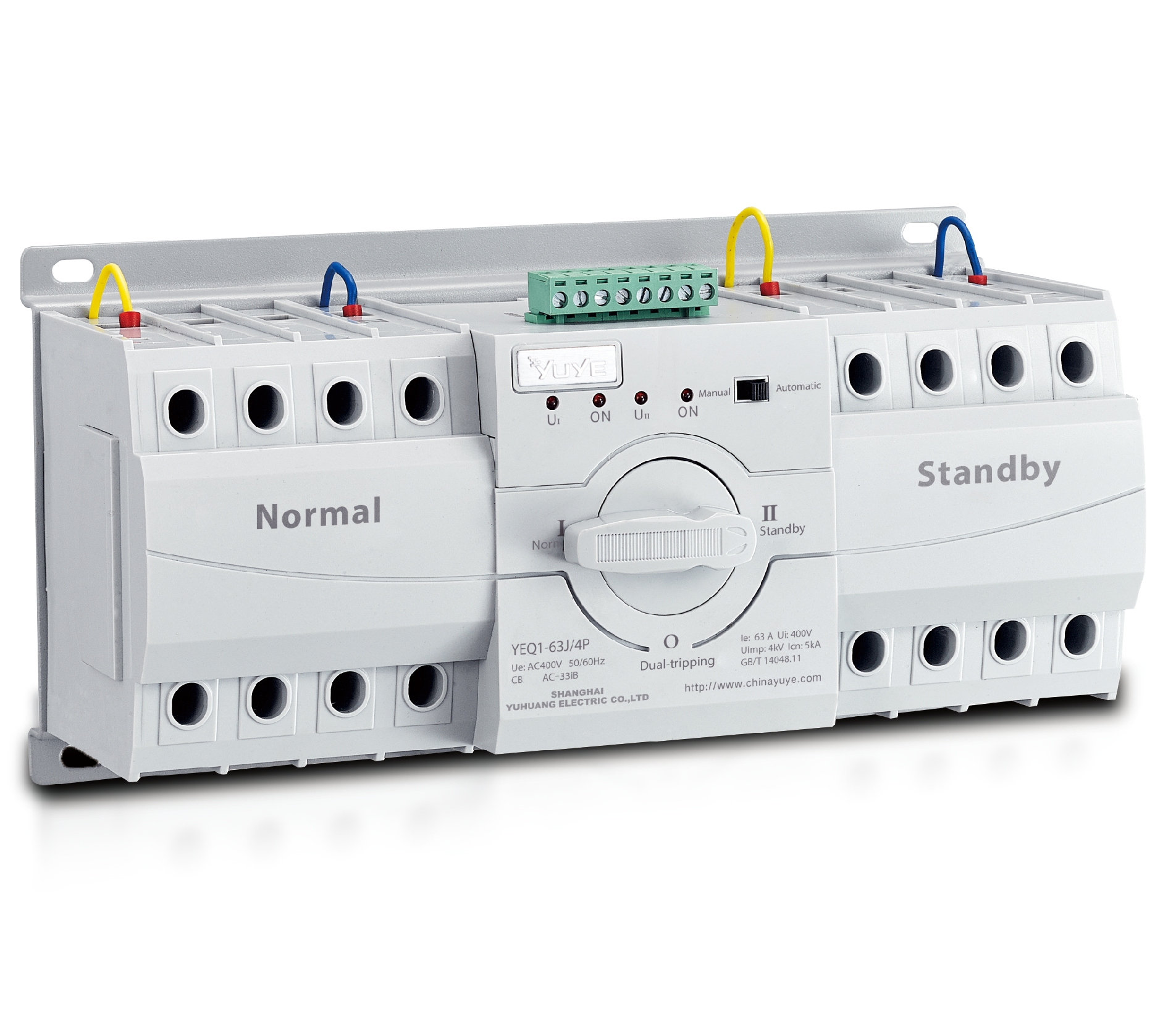
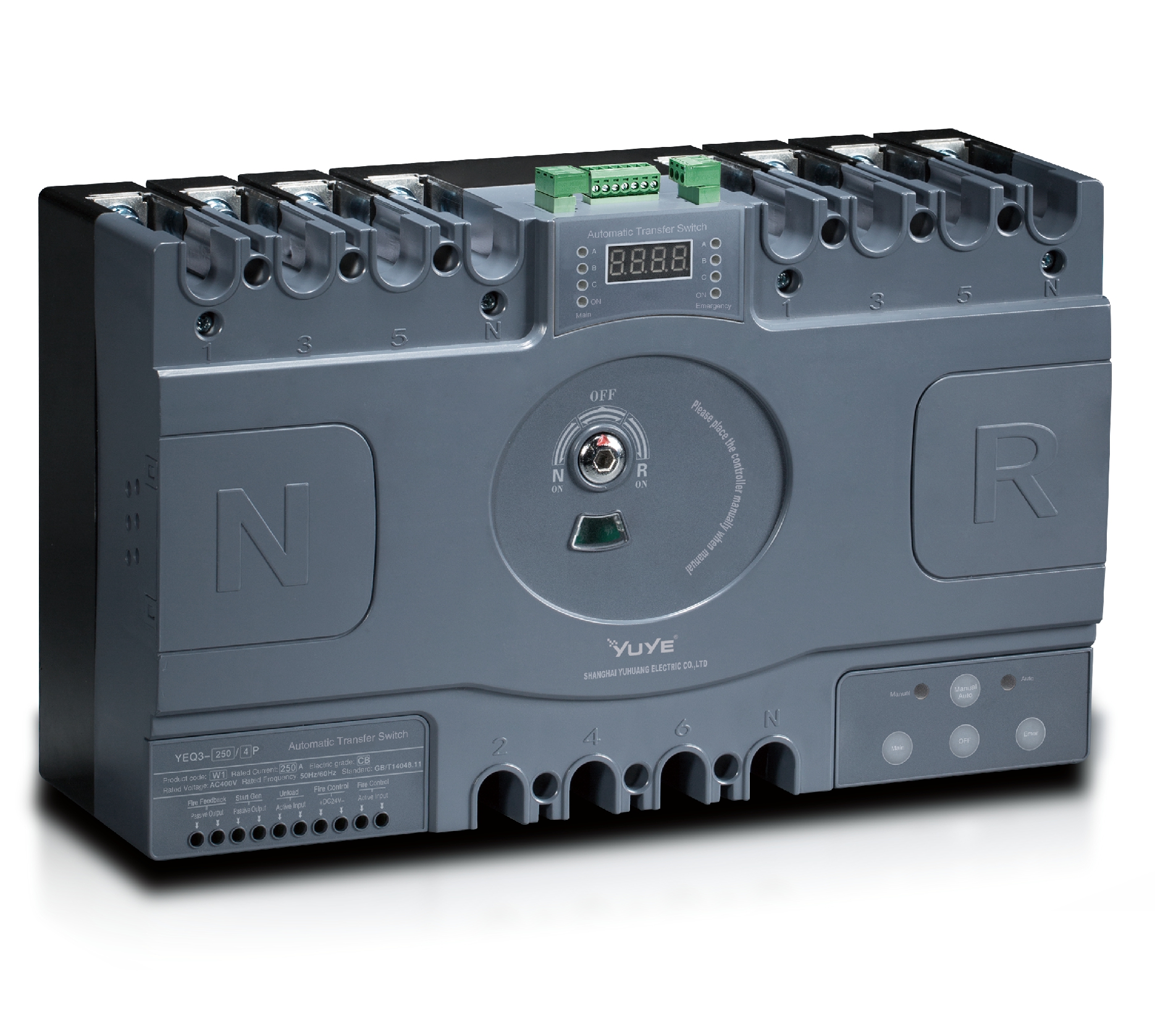
PC ATS YECT1-2000G
PC ATS YES2-63~250GN1
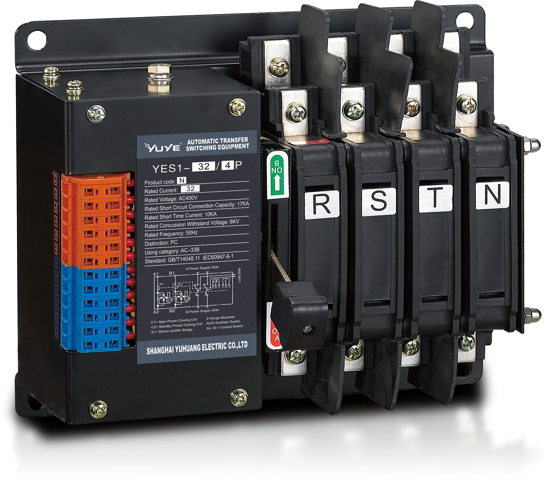
Solenoid-type ATS YES1-32~125N
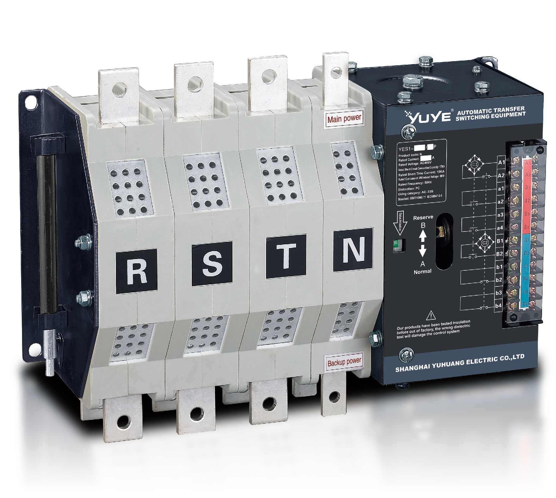
Solenoid-type ATS YES1-250~630N/NT
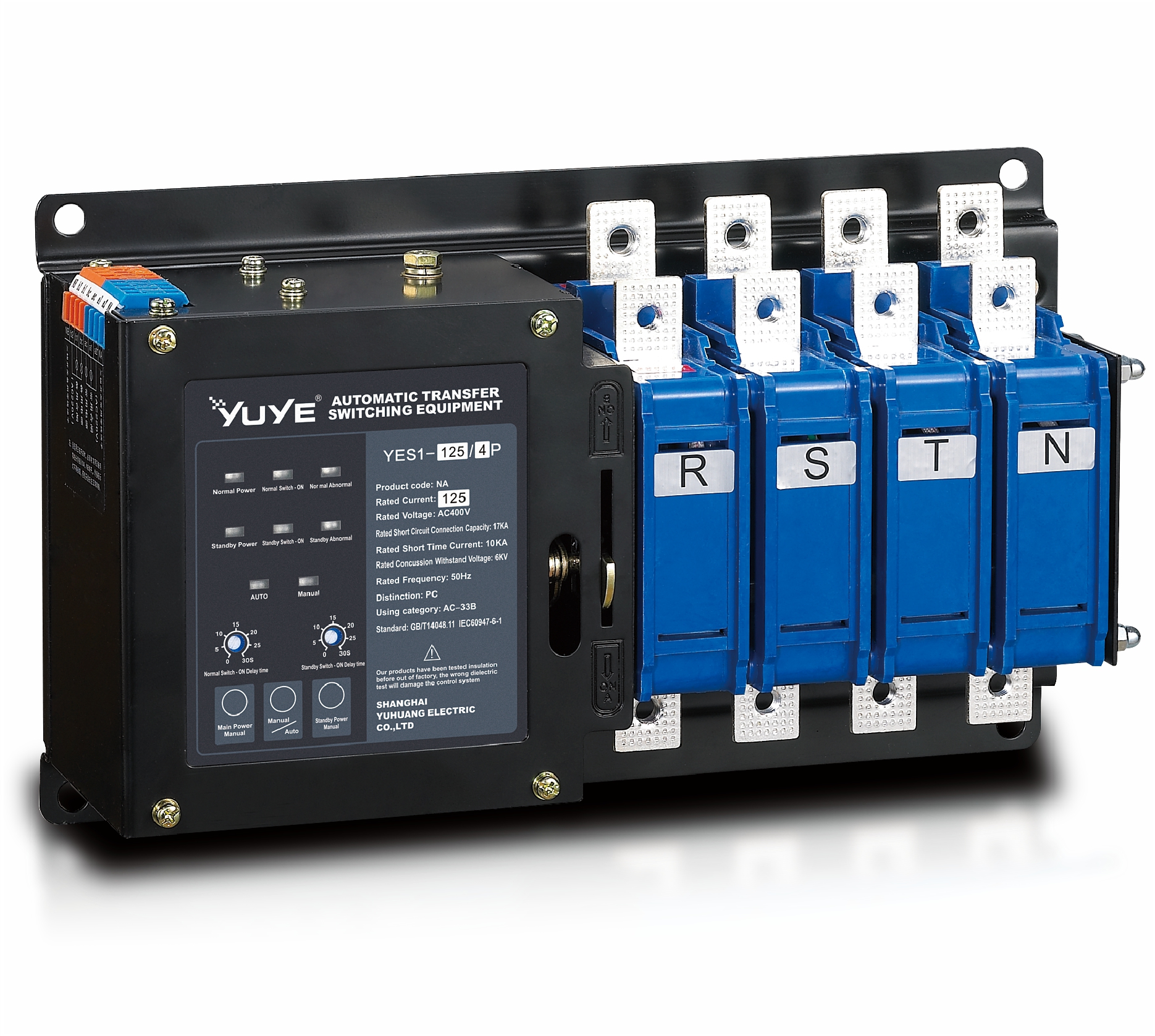
Solenoid-type ATS YES1-32~125NA
Solenoid-type ATS YES1-63~630SN
Solenoid-type ATS YES1-1250~4000SN
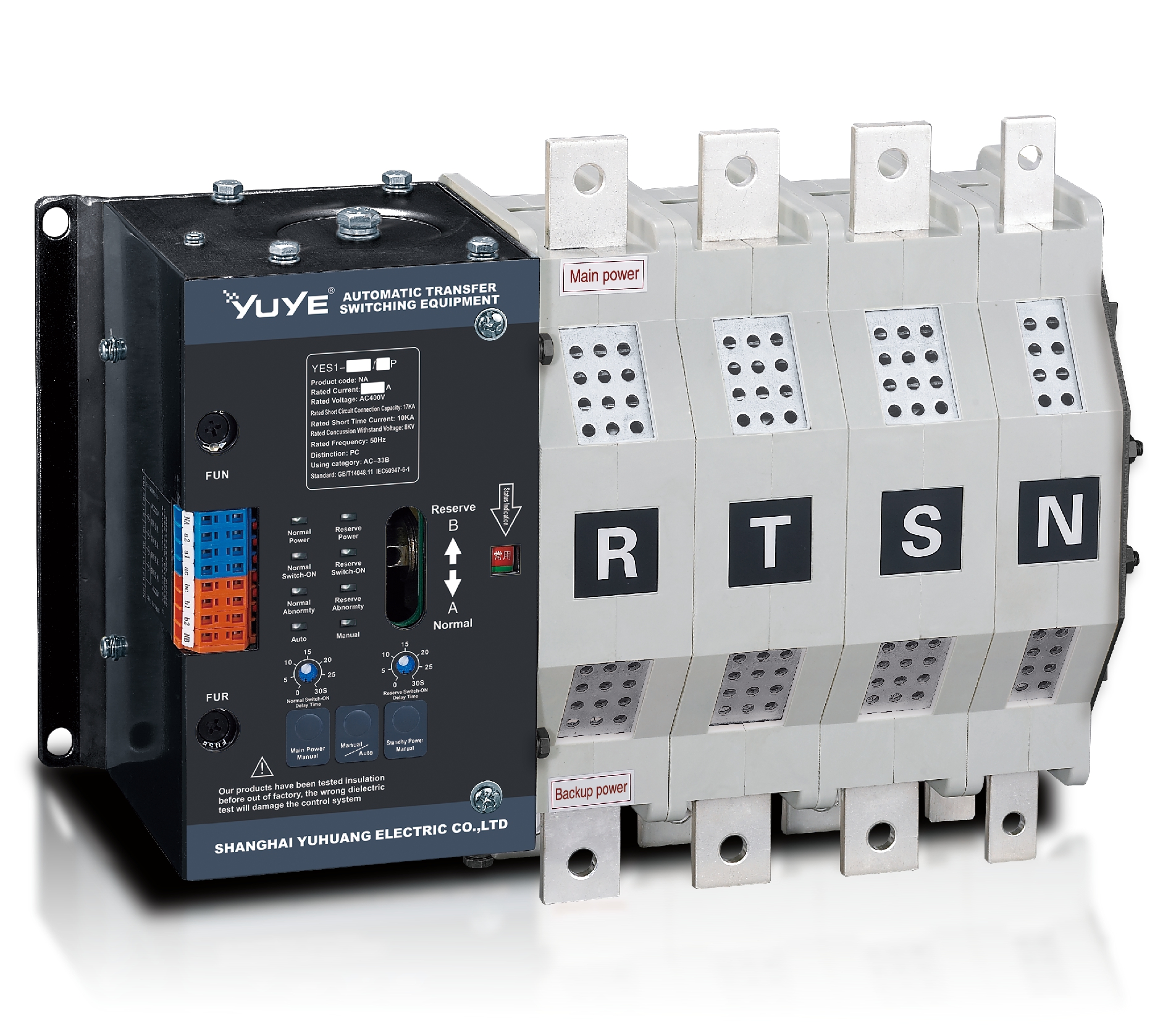
Solenoid-type ATS YES1-250~630NA/NAT
Solenoid-type ATS YES1-63NJT
PC ATS YES1-100~1600GN1/GN/GNF
PC ATS YES1-2000~3200GN/GNF
PC ATS YES1-100~3200GA1/GA
Solenoid-type ATS YES1-63~630SA
Solenoid-type ATS YES1-63~630L/LA
Solenoid-type ATS YES1-63~630LA3
Solenoid-type ATS YES1-63MA
PC ATS YES1-630~1600M
PC ATS YES1-3200Q
Solenoid-type ATS YES1-4000~6300Q
CB ATS YEQ1-63J
CB ATS YEQ2Y-63
CB ATS YEQ3-63W1
CB ATS YEQ3-125~630W1
ATS controller Y-700
ATS Controller Y-700N
ATS Controller Y-701B
ATS Controller Y-703N
ATS Controller Y-800
ATS Controller W2/W3 Series
ATS switch Cabinet floor-to-ceiling
ATS switch cabinet
JXF-225A power Cbinet
JXF-800A power CbinetThink of an Automatic Transfer Switch as that quiet hero inside a reliable backup power setup. It's the one keeping an eye on your utility power, ready to step in whenever there's a hiccup. When the grid fails, it quickly switches the loads over to a generator. And when normal power comes back? No worries—it's smart enough to switch everything back safely and smoothly.
Now, at first glance, that all sounds pretty straightforward. But trust me, it’s not always so simple in practice. Things like timing, voltage levels, frequency, phase alignment, and which loads take priority really matter. Imagine you're in a hospital operating room, a data center, or even a factory—careless switching isn’t an option there. The switch has to respond fast when needed, but also avoid overlapping power sources that could cause damage.
John Camara, a pro in power systems from ASCO Power Technologies, puts it nicely: he calls the device "the decision point between normal and emergency power." Honestly, that sums it up pretty well. The switch itself doesn’t produce electricity—it's just the control that decides when power switches from one source to another.
To get a better grip on how it works, picture this: a generator kicks in next to the main panel during a nighttime outage. The switch picks up on the utility failure, fires up the generator, makes sure everything’s stable, and then transfers the power to the circuits that need it. So, the lights come back on, and critical equipment keeps running without interruption.
But here’s the thing—good systems aren’t just about the switch cabinet and a control panel. Engineers also need to consider things like short-circuit ratings, installation conditions, how easy it is to service, and whether the generator can handle the load. Standards like NFPA 110 can help guide emergency backup plans, but local codes and requirements are just as important and need careful review.
This article takes a closer look at how automatic transfer switches work, where they’re used, and what features you should pay attention to. Plus, it questions a common misconception: just because it’s automatic doesn’t mean it’s maintenance-free. Contacts wear out, batteries weaken over time, and testing can sometimes get overlooked. Keeping these systems reliable means choosing the right equipment, having professionals install it properly, scheduling routine inspections, and honestly evaluating how it’s performing in real-life conditions.
An automatic transfer switch is an electrical device that moves a building’s critical load between two power sources. It commonly connects utility power with a standby generator. The switch continuously checks incoming voltage and frequency. If the normal supply fails, it sends a start signal to the generator. After the backup source becomes stable, the switch transfers the load.
The process usually takes several seconds. That delay protects equipment from unstable generator output. When utility power returns, the switch waits before reconnecting. This prevents a brief voltage fluctuation from causing another transfer. Inside the enclosure, contactors, sensors, timers, and control circuits work together. Indicator lights can show the active source and transfer status. That small panel can reveal a great deal.
Correct sizing matters. The switch must match the system voltage, current, fault rating, and load type. Motors and medical equipment may require careful transfer settings. A practical inspection should include wiring checks, alarm testing, battery condition, and a simulated power failure. Never assume the generator alone proves the system works. That assumption can fail. Testing under real load is useful, but it must follow local electrical requirements and qualified procedures. Poor maintenance may leave contacts worn, settings incorrect, or control batteries weak. The device looks simple from outside. Its reliability depends on details inside.
What Is an Automatic Transfer Switch?
How an Automatic Transfer Switch Works
An automatic transfer switch connects essential electrical loads to two power sources. Usually, one source is the utility supply, while the other is a standby generator. Its controller constantly monitors voltage, frequency, and phase conditions. When utility power fails or becomes unstable, the switch identifies the problem within seconds. It then sends a start signal to the generator.
The generator needs time to reach stable speed and voltage. During this delay, the transfer switch keeps the load disconnected from the backup source. Once readings meet programmed limits, motor-driven contacts move from the utility position to the generator position. Mechanical and electrical interlocks prevent both sources from connecting together. That detail matters because an accidental connection could seriously damage equipment or endanger workers.
When utility power returns, the controller watches it for a set period. This delay helps prevent rapid switching during a temporary voltage recovery. The switch then transfers the load back and signals the generator to cool down before stopping. In field inspections, loose control wires, weak batteries, and incorrect delay settings often cause trouble. A clean cabinet does not prove reliable operation. Testing should include simulated power loss, contact movement, alarm functions, and retransfer behavior. Some installations also need manual operation, but manual control can expose gaps in training and maintenance. Real systems are dependable only when installation records, scheduled testing, and careful observations support the design.
An automatic transfer switch monitors the normal utility source and transfers the connected load to a standby source when utility power fails. This representative timeline shows source availability and load transfer during a typical standby-generator sequence.
The utility source fails at approximately 1 second. After the generator starts and reaches acceptable voltage and frequency, the switch transfers the load at approximately 13.2 seconds. Actual detection, generator-start, stabilization, and transfer times depend on system settings and installation requirements.
An automatic transfer switch, or ATS, moves electrical loads between a normal source and a backup source. Its controller continuously checks voltage, frequency, and phase conditions. If the primary supply fails, sensing relays send a start signal to the generator. After stabilization, the switching mechanism transfers the load. Mechanical and electrical interlocks prevent both sources from connecting simultaneously.
The main components include source terminals, a microprocessor controller, power contacts, an enclosure, neutral switching, and manual controls. Bypass-isolation equipment can support maintenance without interrupting critical loads. Communication ports also send alarms, transfer status, and test results to a monitoring system. According to Uptime Institute’s 2024 Annual Outage Analysis, 54% of respondents said their most recent outage cost more than $100,000. That figure makes dependable transfer logic more than a convenience.
Small details matter.
Tips: Check sensing thresholds, transfer delays, contact wear, and battery readiness during scheduled tests. Confirm that the neutral arrangement matches the site’s grounding design. A commissioning checklist should record actual voltage readings, not only pass or fail results. Field conditions can expose weaknesses that drawings miss. That assumption deserves challenge. Selection should also consider short-circuit ratings, available fault current, enclosure conditions, and the switching duty cycle. NFPA 110 requirements can guide emergency and standby power installations, but local electrical rules still require professional review.
An automatic transfer switch moves electrical loads between normal and backup power. Its type affects transfer speed, equipment stress, and power continuity. The most common design is the open-transition switch. It disconnects the normal source before connecting the generator. This break-before-make method is simple and widely used, but sensitive equipment may briefly lose power.
A delayed-transition switch adds a programmed neutral interval. This allows motors, transformers, and residual voltage to decay before reconnection. It can reduce inrush current, especially in facilities with large mechanical loads. A closed-transition switch briefly connects both sources before separation. It can provide nearly uninterrupted transfer, but it requires accurate synchronization and stricter system coordination. Static transfer switches use power semiconductors rather than mechanical contacts. They can transfer critical loads within milliseconds, although heat management and upstream protection need careful review.
Uptime Institute’s 2024 Global Data Center Survey reported that 53% of respondents experienced an outage within the previous three years. Power-related failures remain a major concern. That figure makes transfer strategy more than a purchasing detail.
Tips: Match the switch to the load, not only the generator size. Check neutral switching, short-circuit ratings, maintenance access, and transfer-test records. One detail is often missed: a fast switch cannot correct poor grounding or unstable source frequency. The boundary between “adequate” and “resilient” is not always neat. Review real load behavior before final selection.
An automatic transfer switch (ATS) moves electrical loads from a primary source to a standby source. It detects voltage loss, starts the backup generator, and transfers power automatically. The process usually takes seconds, not minutes. Critical systems cannot depend on manual switching.
Data centers are a major application. The International Energy Agency reported that data centers consumed about 240 terawatt-hours globally in 2022. This demand may exceed 1,000 terawatt-hours by 2026 in some scenarios. An ATS helps protect servers, cooling equipment, access controls, and network systems during utility failures. Uptime Institute’s 2024 Annual Outage Analysis also reported that more than half of serious outages created losses above 100,000 dollars. That figure makes automatic power transfer a practical risk-control measure, not merely an engineering preference.
Hospitals use ATS units for operating rooms, intensive care areas, elevators, fire systems, and medical refrigeration. Manufacturing plants depend on them for programmable controls, pumps, conveyors, and safety equipment. They also appear in airports, telecommunications facilities, office buildings, farms, and large residences. In each setting, the load profile differs. A hospital may need rapid transfer, while a factory may require coordination with motor starting currents. The switch is not magic. Poor maintenance, undersized generators, or incorrect testing can still cause failure. NFPA 110 guidance emphasizes regular inspection and operational testing, yet real sites sometimes treat testing as paperwork. That is where designs should be questioned.
| Data Dimension | Typical Specification or Category | Practical Information |
|---|---|---|
| Basic Function | Automatic source transfer | An automatic transfer switch monitors the normal power source and transfers connected loads to an alternate source when the normal source fails or moves outside configured limits. |
| Primary Power Sources | Utility and standby source | The normal source is commonly the utility supply. The alternate source may be a standby generator, a second utility feeder, an inverter system, or another independent power source. |
| Return-to-Normal Operation | Automatic retransfer | After the normal source becomes stable, the switch can automatically return the load to the normal source following a preset delay. The standby generator may then continue its cool-down cycle before stopping. |
| Transfer Method | Open transition | The original source is disconnected before the alternate source is connected. This break-before-make method prevents the two sources from being connected together through the switch. |
| Transfer Method | Closed transition | The alternate source is connected briefly before the normal source is disconnected. This make-before-break method can reduce interruption, but it requires suitable source synchronization and system controls. |
| Typical Transfer Time | Sub-second to several seconds | The actual time depends on sensing settings, programmed delays, switch design, and the time required for a standby generator to start and stabilize. Many systems use adjustable time delays to avoid transfers caused by momentary disturbances. |
| Voltage Configuration | Low-voltage and medium-voltage systems | Automatic transfer switches are available for different system voltages and phase arrangements. The selected unit must match the system voltage, frequency, number of poles, and grounding arrangement. |
| Load Capacity | Rated by current and switching duty | Common selection factors include continuous current rating, short-circuit withstand capability, number of poles, load type, and the required transfer duty. The switch rating should meet or exceed the connected load requirements. |
| Control Functions | Voltage, frequency, and delay monitoring | Controllers can monitor source voltage and frequency, detect source failure, initiate generator start signals, apply transfer and retransfer delays, and provide status or alarm contacts. |
| Healthcare Facilities | Critical and life-safety circuits | Hospitals, clinics, laboratories, and care facilities use transfer systems to support essential medical equipment, emergency lighting, fire-protection systems, communication equipment, and other designated loads. |
| Commercial Buildings | Emergency and legally required loads | Office buildings, retail properties, hotels, and public buildings may use automatic transfer switches for emergency lighting, elevators, fire alarms, security systems, data networks, and selected mechanical services. |
| Industrial Facilities | Process continuity and equipment protection | Factories and processing plants use automatic transfer systems to support control systems, production equipment, safety systems, refrigeration, pumps, and other loads where an outage could create safety or operational problems. |
| Data and Communication Sites | Critical digital infrastructure | Data centers, telecommunications facilities, and network rooms may use transfer equipment as part of a broader power system that can include generators, uninterruptible power supplies, and redundant distribution paths. |
| Residential and Small Facilities | Backup power for essential circuits | Homes, small offices, and small commercial sites may use an automatic transfer switch to connect selected circuits or an entire electrical service to a standby generator or other approved backup source. |
| Outdoor and Remote Applications | Distributed and unattended sites | Water facilities, traffic systems, remote communication sites, agricultural operations, and temporary infrastructure can use automatic transfer switches where reliable operation is needed without manual intervention. |
| Installation Requirements | System compatibility and code compliance | Installation requires correct coordination with protective devices, grounding and bonding arrangements, source capacity, enclosure conditions, maintenance access, and applicable electrical and emergency-power requirements. |

Note: Actual ratings, transfer times, environmental limits, and control features vary by application and equipment design. Selection and installation should be completed by qualified electrical professionals in accordance with applicable local requirements.
An automatic transfer switch moves electrical loads between a primary source and a standby source. During an outage, it detects voltage loss and starts the transfer sequence. Selection should begin with the load, not the enclosure. Check continuous current, inrush current, voltage, frequency, number of poles, and available short-circuit rating. Confirm whether the neutral must switch. That detail is often missed.
Choose a transfer mode that suits the equipment. Open transition prevents source overlap, while closed transition can reduce interruption but requires careful system coordination. Review sensing delays, bypass features, environmental protection, and controller alarms. A qualified electrician should verify installation, grounding, clearances, and local code requirements. A clean panel does not prove correct wiring. It is worth checking.
Tips: Inspect terminals, contacts, insulation, and signs of heat during scheduled maintenance. Test automatic transfer under controlled conditions, then record transfer time and abnormal sounds. Exercise the switch even when outages are rare. Keep the enclosure dry and unobstructed. Never rely only on indicator lights; measure source voltage with approved equipment. Follow the equipment instructions and use proper isolation procedures before internal work. Maintenance records should include test dates, readings, defects, and corrective actions. If a test fails, investigate the cause instead of repeatedly resetting the controller.
An ATS Switch Cabinet Floor-to-Ceiling provides reliable power transfer for modern electrical systems where continuity and safety are essential. Designed with dual-circuit power inputs, it automatically detects changes in the primary power source and transfers the load to the available supply according to the selected switching mode. With a broad capacity range from 63A to 4000A, the cabinet can be configured to match different downstream load requirements in commercial buildings, industrial facilities, data centers, and infrastructure projects.
Built for dependable operation, the cabinet uses high-quality switching components, integrated surge protection, and comprehensive factory electrical performance testing. A 4.3-inch touch screen or smart meter enables operators to monitor current, power, energy consumption, and other key operating information in real time. The floor-standing structure supports maintenance from both the front and rear, helping simplify inspection, troubleshooting, and component replacement in confined electrical rooms. Complete quality certifications further support consistent manufacturing standards and dependable long-term operation.
It moves essential electrical loads between a normal source and a standby generator. It monitors voltage, frequency, and phase. That is its job.
The switch detects unstable or missing power within seconds. It signals the generator to start. The load remains disconnected until stable readings appear.
Generators need time to reach stable speed and voltage. The delay prevents unstable power from reaching connected equipment. Small delays matter.
Mechanical and electrical interlocks block simultaneous connection. This protects equipment and workers from dangerous source overlap. The detail is easy to underestimate.
Open-transition switches disconnect one source before connecting another. Delayed-transition models add a neutral interval. Closed-transition designs briefly overlap sources. Static models use power semiconductors and can transfer loads within milliseconds.
Static or closed-transition designs can reduce interruption time. Closed transition requires accurate synchronization and careful coordination. Fast transfer cannot fix poor grounding or unstable frequency.
Match it to the actual load, not only the generator size. Check current, inrush current, voltage, frequency, poles, neutral switching, and short-circuit rating. Real load behavior matters.
Inspect terminals, contacts, insulation, batteries, control wires, and heat marks. Simulate power loss under controlled conditions. Record transfer time, alarms, contact movement, and retransfer behavior.
No. A clean cabinet proves little. Hidden wiring faults, weak batteries, and incorrect delays can remain. Repeatedly resetting a failed controller is not a real repair.
An Automatic Transfer Switch is a critical electrical device that automatically changes a facility’s power supply from a primary source to a backup source when an outage, voltage problem, or other disruption occurs. It continuously monitors incoming power, detects abnormal conditions, and transfers the connected load to an alternative source, such as a generator or secondary utility line. Once the primary source becomes stable again, it can return the load through a controlled retransfer process.
The main components typically include a monitoring controller, switching mechanism, power terminals, protective features, and a manual operation option. Common types include open-transition, closed-transition, delayed-transition, and bypass-isolation designs, each suited to different continuity and safety requirements. Automatic Transfer Switches are widely used in homes, data centers, hospitals, industrial facilities, commercial buildings, and emergency systems. Choosing the right unit requires evaluating voltage, current capacity, phase configuration, transfer speed, installation conditions, and load characteristics. Regular inspection, testing, cleaning, and professional maintenance help ensure dependable operation when backup power is needed.