
 PC ATS YECT1-2000G
 PC ATS YES2-63~250GN1
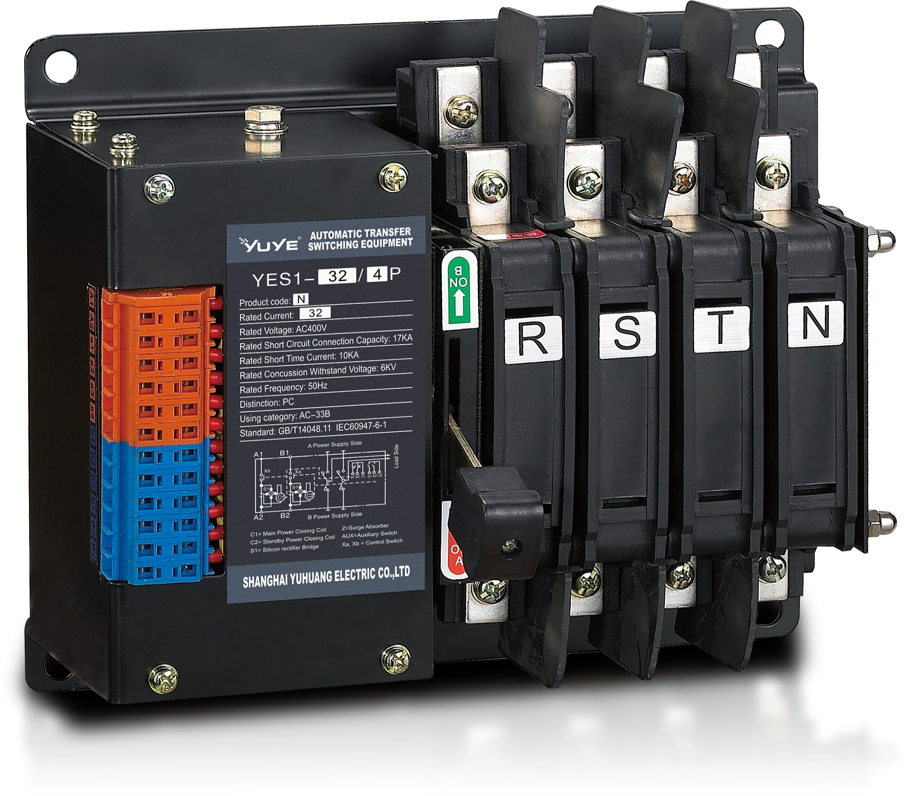 Solenoid-type ATS YES1-32~125N
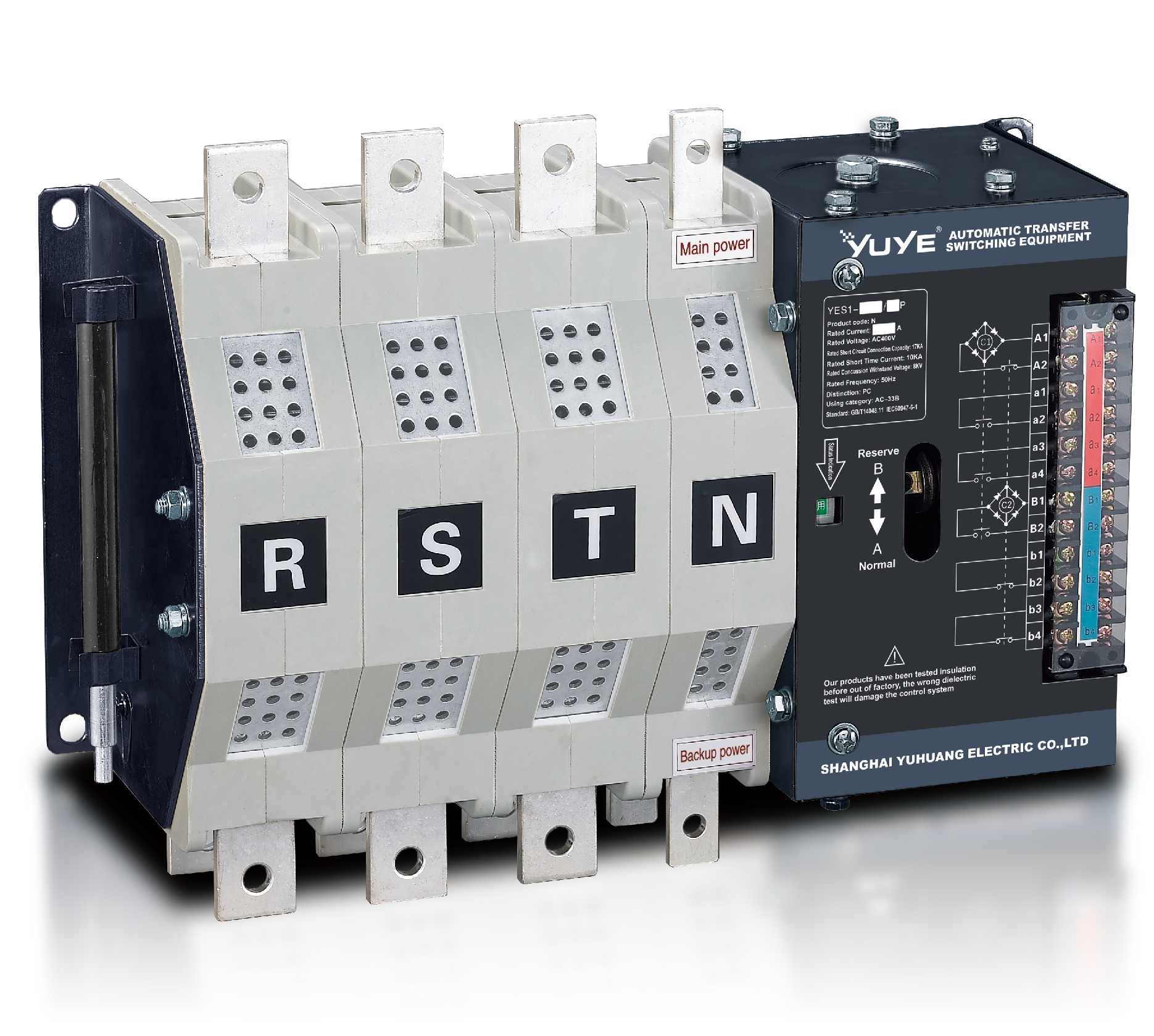 Solenoid-type ATS YES1-250~630N/NT
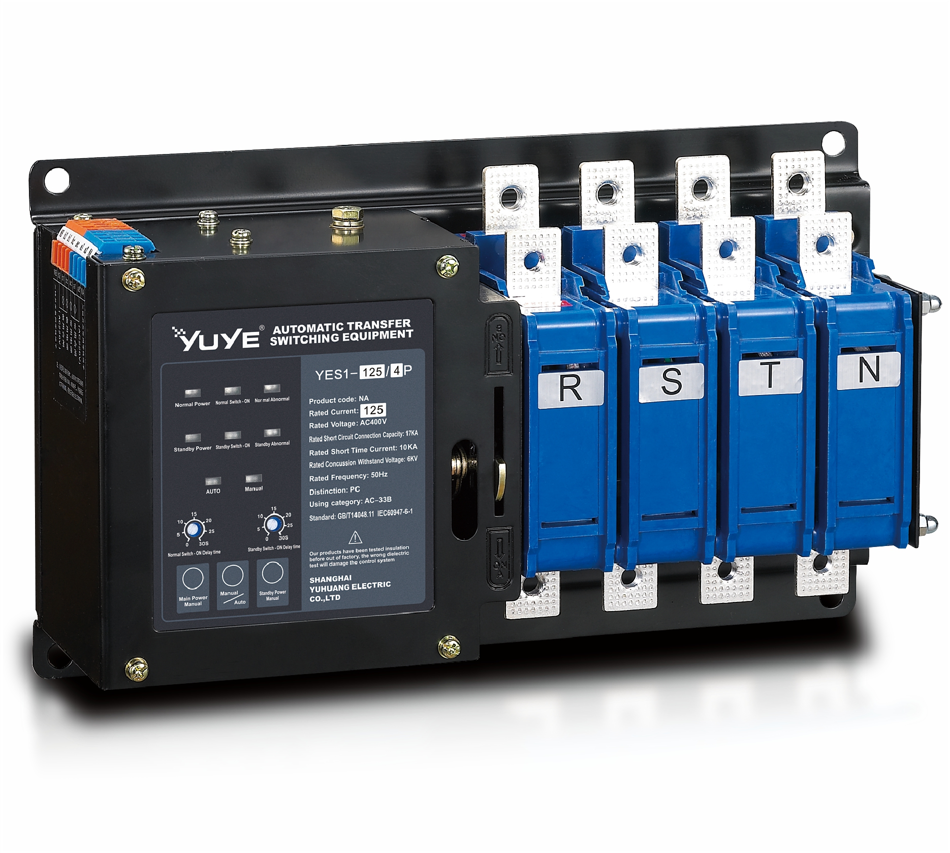 Solenoid-type ATS YES1-32~125NA
 Solenoid-type ATS YES1-63~630SN
 Solenoid-type ATS YES1-1250~4000SN
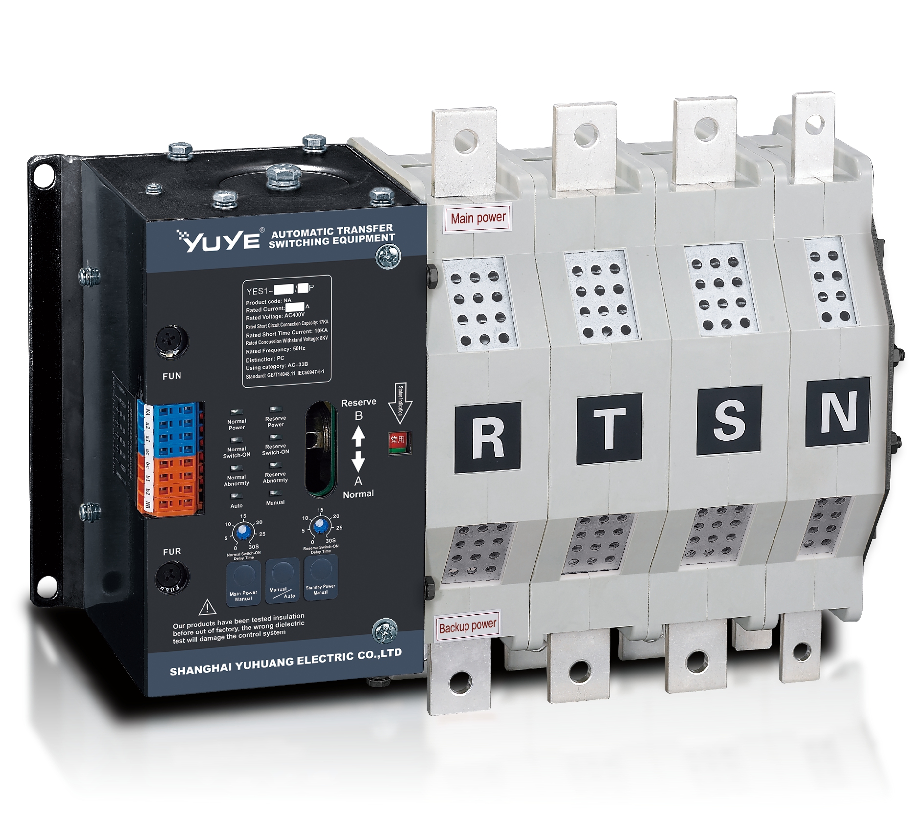 Solenoid-type ATS YES1-250~630NA/NAT
 Solenoid-type ATS YES1-63NJT
 PC ATS YES1-100~1600GN1/GN/GNF
 PC ATS YES1-2000~3200GN/GNF
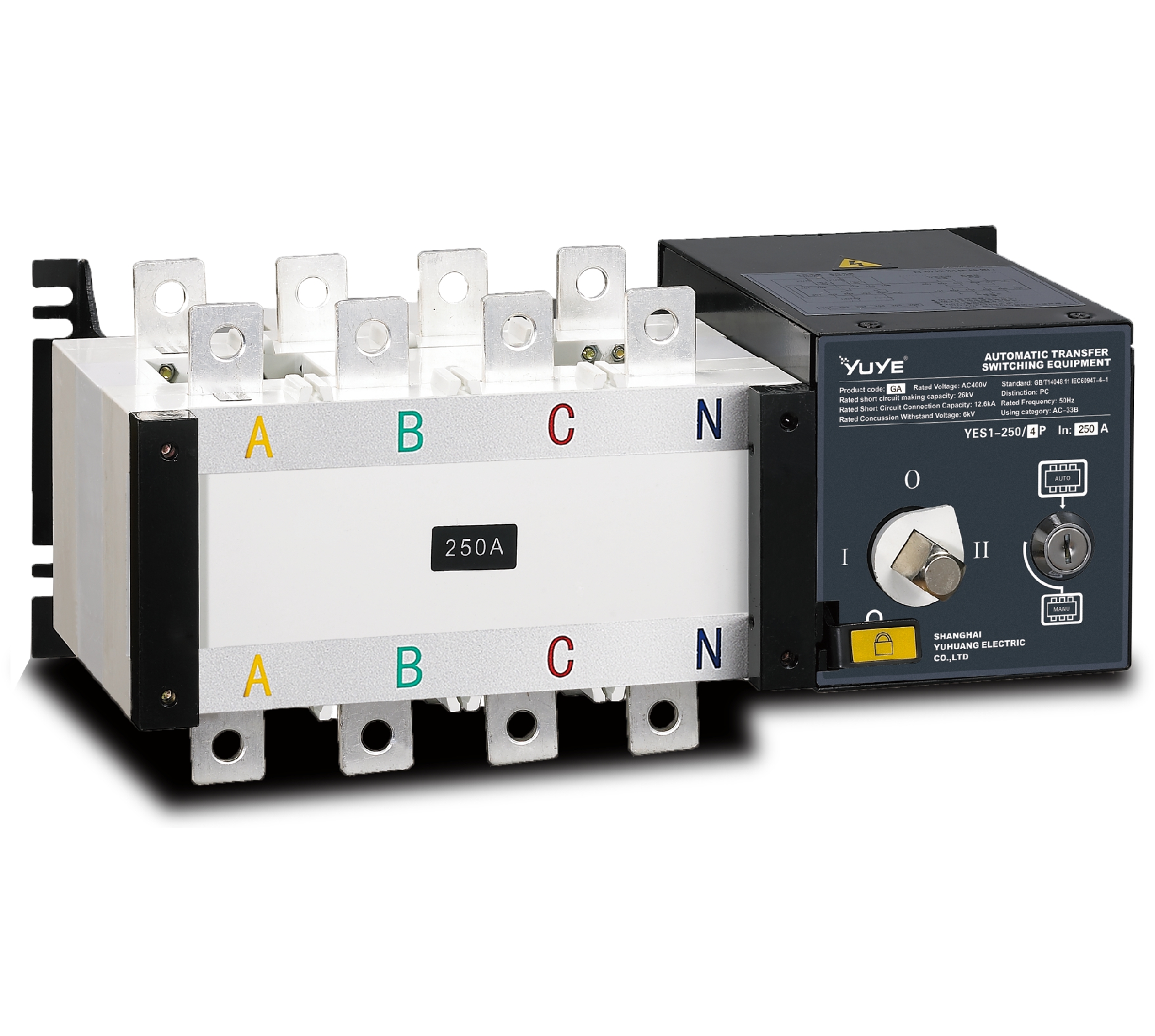 PC ATS YES1-100~3200GA1/GA
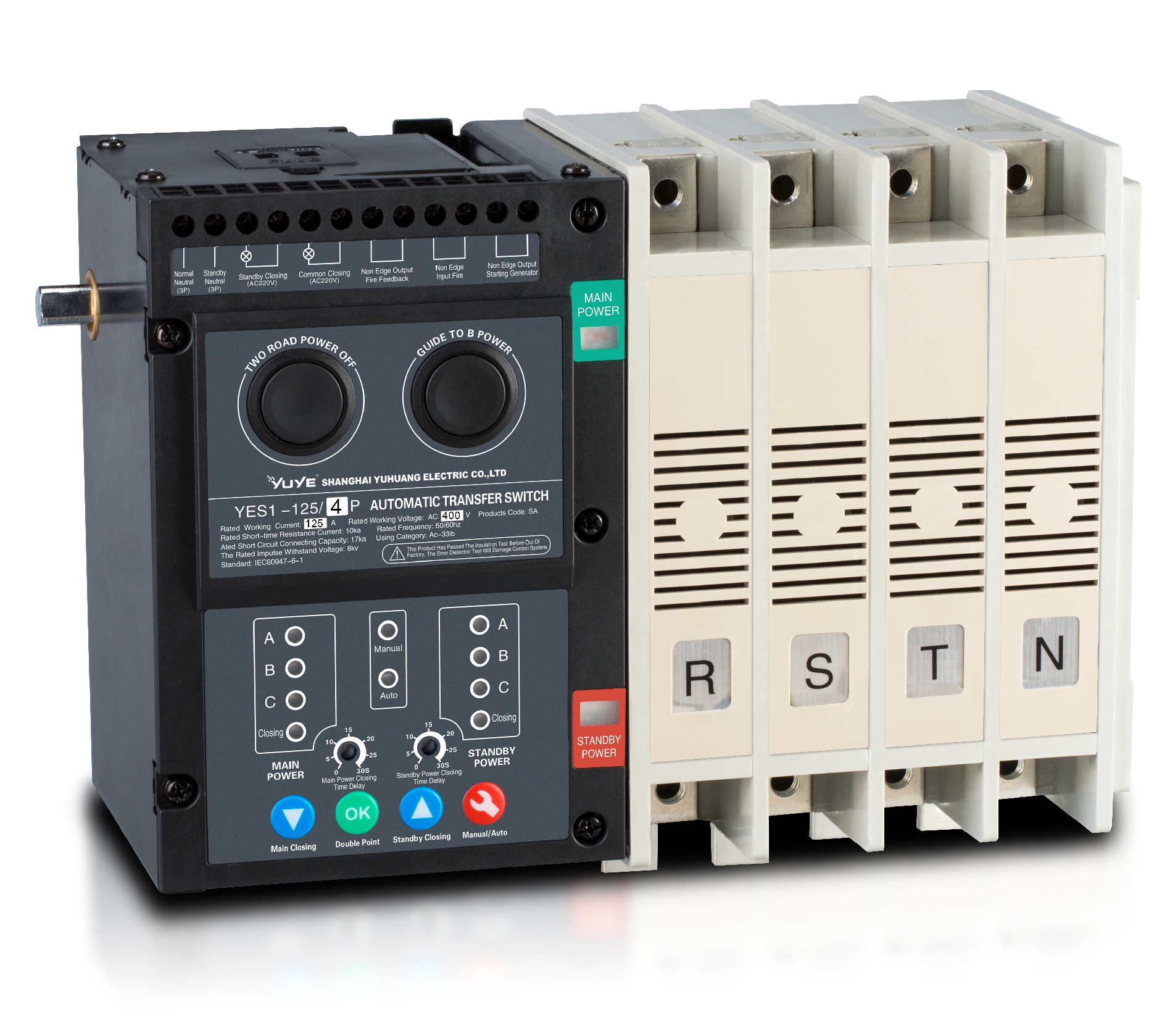 Solenoid-type ATS YES1-63~630SA
 Solenoid-type ATS YES1-63~630L/LA
 Solenoid-type ATS YES1-63~630LA3
 Solenoid-type ATS YES1-63MA
 PC ATS YES1-630~1600M
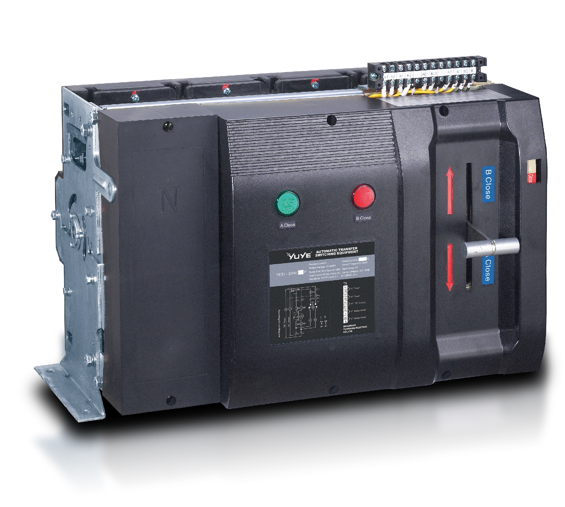 PC ATS YES1-3200Q
 Solenoid-type ATS YES1-4000~6300Q
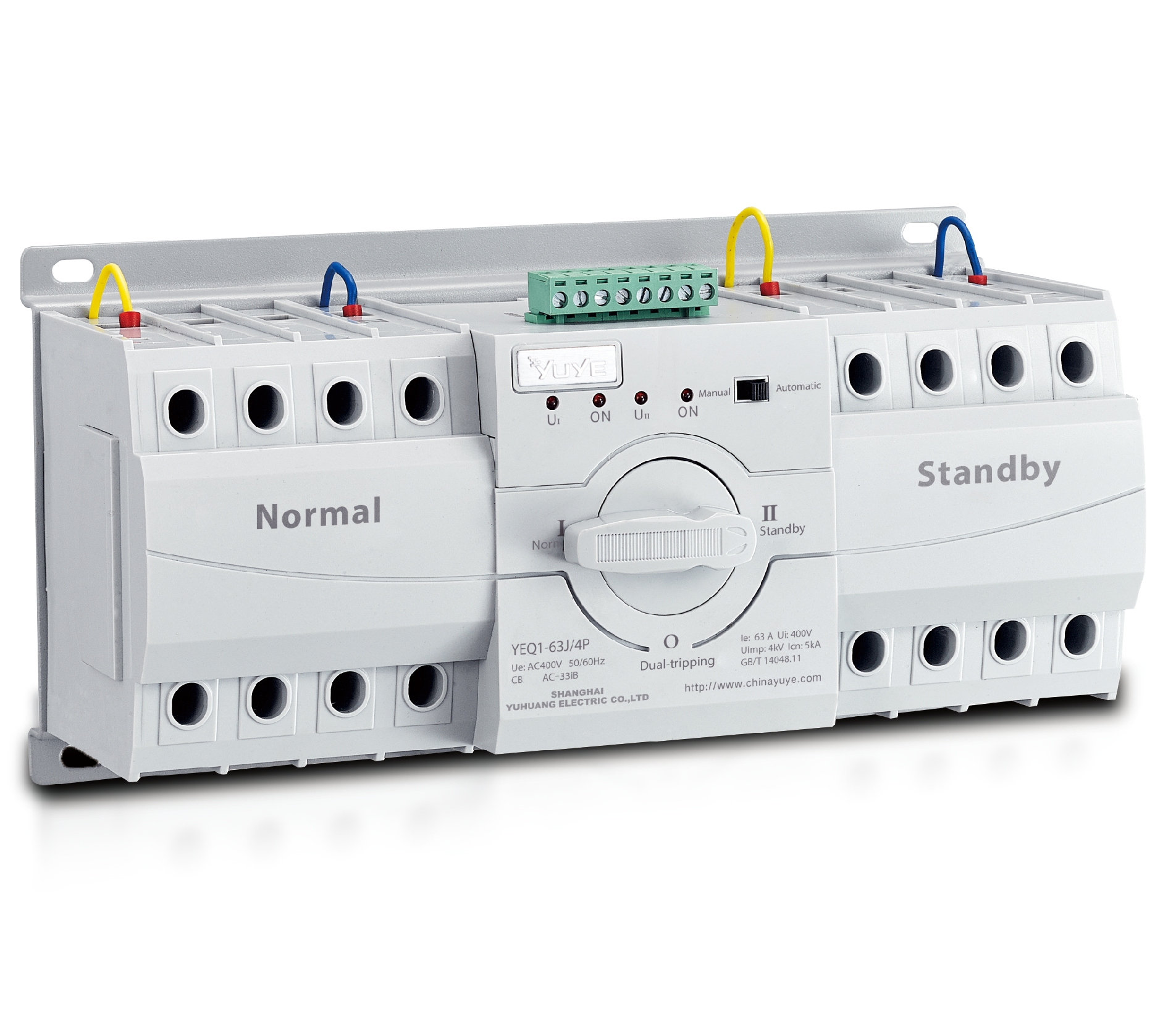 CB ATS YEQ1-63J
 CB ATS YEQ2Y-63
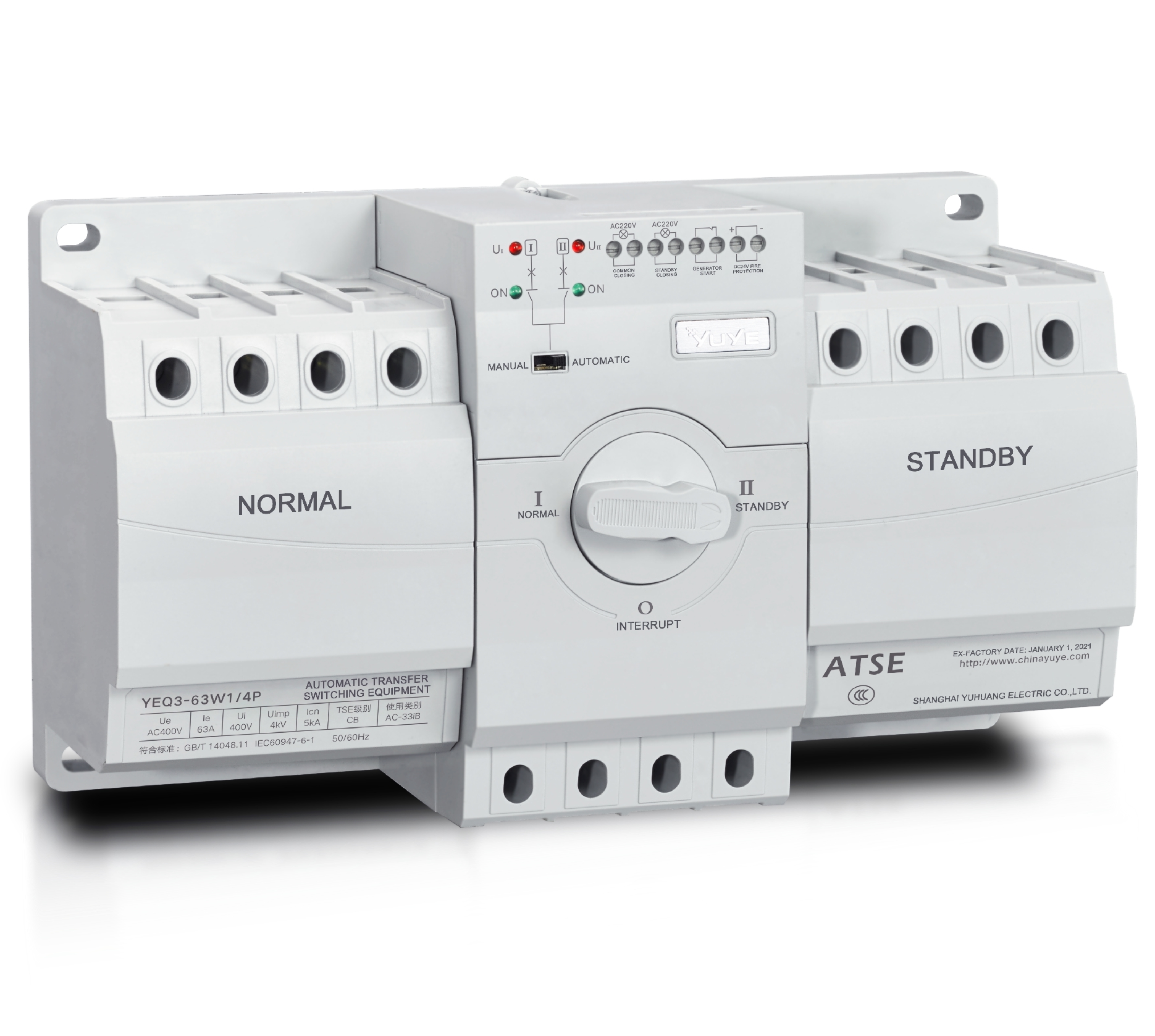 CB ATS YEQ3-63W1
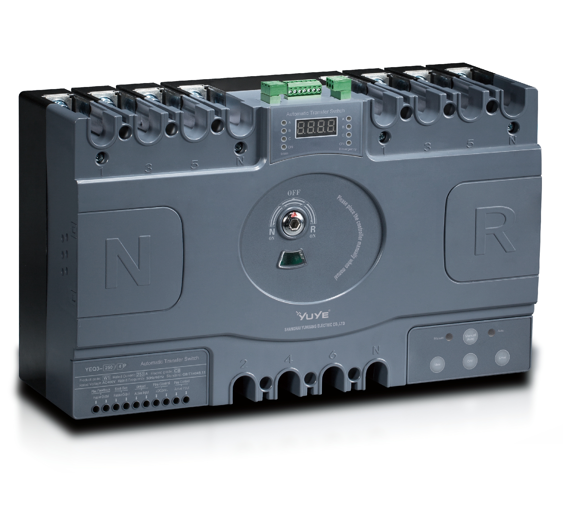 CB ATS YEQ3-125~630W1
 ATS controller Y-700
 ATS Controller Y-700N
 ATS Controller Y-701B
 ATS Controller Y-703N
 ATS Controller Y-800
 ATS Controller W2/W3 Series
 ATS switch Cabinet floor-to-ceiling
 ATS switch cabinet
 JXF-225A power Cbinet
 JXF-800A power Cbinet
 YEM3-125~800 Plastic Shell Type MCCB
 YEM3L-125~630 Leakage Type MCCB
 YEM3Z-125~800 Adjustable Type MCCB
 YEM1-63~1250 Plastic Shell Type MCCB
 YEM1E-100~800 Electronic Type MCCB
 YEM1L-100~630 Leakage Type MCCB
 Air Circuit Breaker YEW1-2000~6300
 Air Circuit Breaker YEW3-1600
 Miniature circuit breaker YEMA2-6~100
 Miniature circuit breaker YEB1-3~63
 Miniature circuit breaker YEB1LE-3~63
 Miniature circuit breaker YEPN-3~32
 Miniature circuit breaker YEPNLE-3~32
 Miniature circuit breaker YENC-63~125
 Load isolation switch YGL-63~3150
 Load Isolation Switch YGL2-63~3150
 DC relay YDC-P20
 DC relay YDC-P250
 DC relay YDC-P400
 DC relay MDC-300M
 DC relay YDC-M400
 DC Isolation Switch YEGL3D-630
 YECPS2-45~125 LCD
 YECPS-45~125 Digital
 CNC Milling/Turning-OEM
A transfer switch allows electrical equipment to change from one power supply to another. In most low-voltage distribution systems, it connects a normal supply and a standby supply. When the normal supply fails, the load can be moved to the standby source instead of remaining without power.
A Three-Phase Switch is commonly used in hospitals, telecom rooms, elevators, fire protection systems, emergency lighting circuits, and industrial distribution panels. Its job is straightforward, but the switching process must be carefully controlled. Only one supply should feed the load at a time.
1. Manual or Automatic?
The first choice is between manual and automatic operation.
A manual transfer switch is operated with a handle or lever. It is simple, affordable, and suitable for places where an immediate changeover is unnecessary. Maintenance circuits are a typical example, especially when someone needs to inspect the site before switching.
An automatic transfer switch, usually called an ATS, does the work without an operator. Its controller monitors the normal supply. If the voltage drops outside the permitted range or disappears completely, the ATS waits for the set delay and then transfers the load to the standby supply.
The delay matters. A brief voltage dip should not trigger a transfer every time. Once the normal supply becomes stable again, the ATS can either return automatically or remain on the standby supply until someone resets it. The right setting depends on the site’s operating procedure.
Transfer switches are also available with different pole arrangements:
- 3P: Switches the three phase conductors while leaving the neutral unswitched.
- 4P: Switches the neutral as well as the phase conductors.
A 4P model is not automatically the better option. The decision depends on the neutral arrangement, grounding method, and the possibility of circulating current between the two supplies.
Some switches have only two positions: normal and standby. Others include an “OFF” position that disconnects both sources. This extra position can be useful during maintenance.
2. What Is Inside the Switch?
The inside of a Three-Phase Switch is built around four main parts: the enclosure, contacts, operating mechanism, and auxiliary devices.
The enclosure supports the internal components and protects them from the surrounding environment. For a clean indoor panel, IP20 may be sufficient. Dust, moisture, or outdoor conditions may call for a higher IP rating and a suitable enclosure.
The contacts carry the load current. Moving and fixed contacts open or close the circuit, while an arc chute helps cool and extinguish the arc produced during interruption. Contact material, contact pressure, and operating speed all affect service life. A switch that opens too slowly may suffer unnecessary contact damage.
Manual models use a handle or lever. Automatic models normally use a motor-driven mechanism controlled by the ATS unit. Spring energy storage is often included so that the contacts move quickly and positively rather than drifting between positions.
Auxiliary contacts and indicator lamps show whether the normal or standby supply is connected. They can also send status signals to a monitoring system. In an ATS, the controller handles voltage detection, transfer delays, operating commands, and interlock logic.
3. How the Transfer Process Works
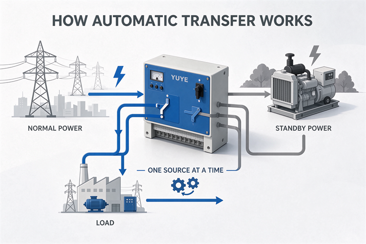
During normal operation, the load is supplied by the normal source. The standby source remains disconnected.
When the controller detects a genuine supply failure, it starts the transfer sequence:
- Wait for the preset delay to expire.
- Open the normal supply side.
- Close the standby supply side.
- Confirm the new switch position.
After the normal supply returns, the switch may transfer back automatically. If automatic return is disabled, it stays on the standby source until an operator intervenes.
The two supplies must never be connected together unintentionally. For this reason, transfer switches use mechanical and electrical interlocks. The mechanical interlock physically prevents both sides from closing at the same time. The electrical interlock provides another layer of protection in the control circuit.
These interlocks are not optional details. They are central to safe changeover operation.
4. How to Select the Right Model
Before ordering a Three-Phase Switch, check the actual load and installation conditions rather than selecting by current rating alone.
Start with the system voltage and frequency. A typical low-voltage system may operate at AC 380 V and 50 Hz, but the switch must match the local supply.
Next, check the rated operational current. It should cover the continuous load current, with due consideration for motor starting and other inrush conditions. An undersized switch may overheat or damage its contacts. An oversized switch usually works, but it adds unnecessary cost.
The utilization category also deserves attention. Categories such as AC-31B, AC-32B, and AC-33B relate to different load duties. AC-33B is commonly associated with motor loads or mixed loads that require more demanding switching operation. The manufacturer’s ratings should be checked against the real application.
Other points to confirm include:
- Three-pole or four-pole construction
- Manual or automatic transfer
- Automatic or manual return
- Short-circuit ratings at the installation point
- Control voltage, such as AC 220 V or DC 24 V
- Auxiliary contacts and remote status signals
- Two-position or three-position operation
- IP rating, ambient temperature, dust, and humidity
For motor circuits, phase sequence is especially important. Both supplies must have the same phase sequence. Otherwise, a motor may reverse after the transfer.
5. Installation and Maintenance Tips
Mount the switch in the orientation specified by the manufacturer and leave enough space for ventilation, wiring, and maintenance. Secure it properly to the panel or mounting surface; the cable terminals should not carry its weight.
Before energizing the equipment, check the phase sequence, neutral connection, protective earth, and terminal torque. Loose connections can create excessive contact resistance and heat.
Routine testing is just as important as correct installation. Operate a manual switch through its positions from time to time and check for smooth movement. Test an ATS by simulating a normal-supply failure, following the site’s safety procedure. Confirm that the delay, transfer, indication, and return functions behave as expected.
During inspection, look for loose fasteners, dust buildup, damaged wiring, and contact wear. Always isolate the equipment before cleaning or internal inspection.
If an ATS fails to transfer, check the control supply and controller first. If it transfers too often, review the voltage thresholds and delay settings. A faulty indicator may be caused by the lamp itself or by an auxiliary contact.
Good performance does not depend on one feature. It comes from selecting the correct ratings, wiring both sources properly, and testing the switch regularly. Those basic steps help ensure that the standby supply is ready when it is actually needed.
