
 PC ATS YECT1-2000G
 PC ATS YES2-63~250GN1
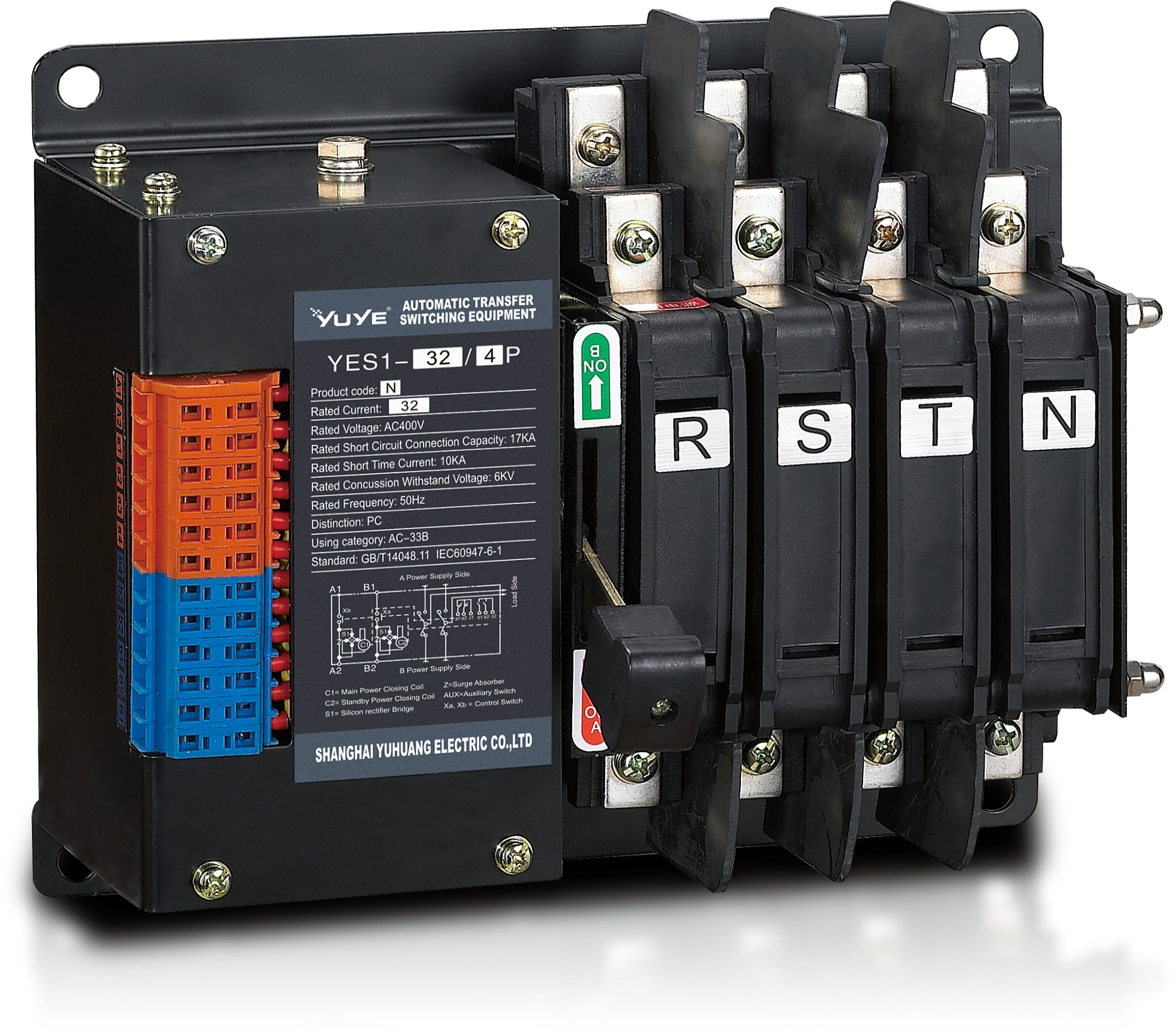 Solenoid-type ATS YES1-32~125N
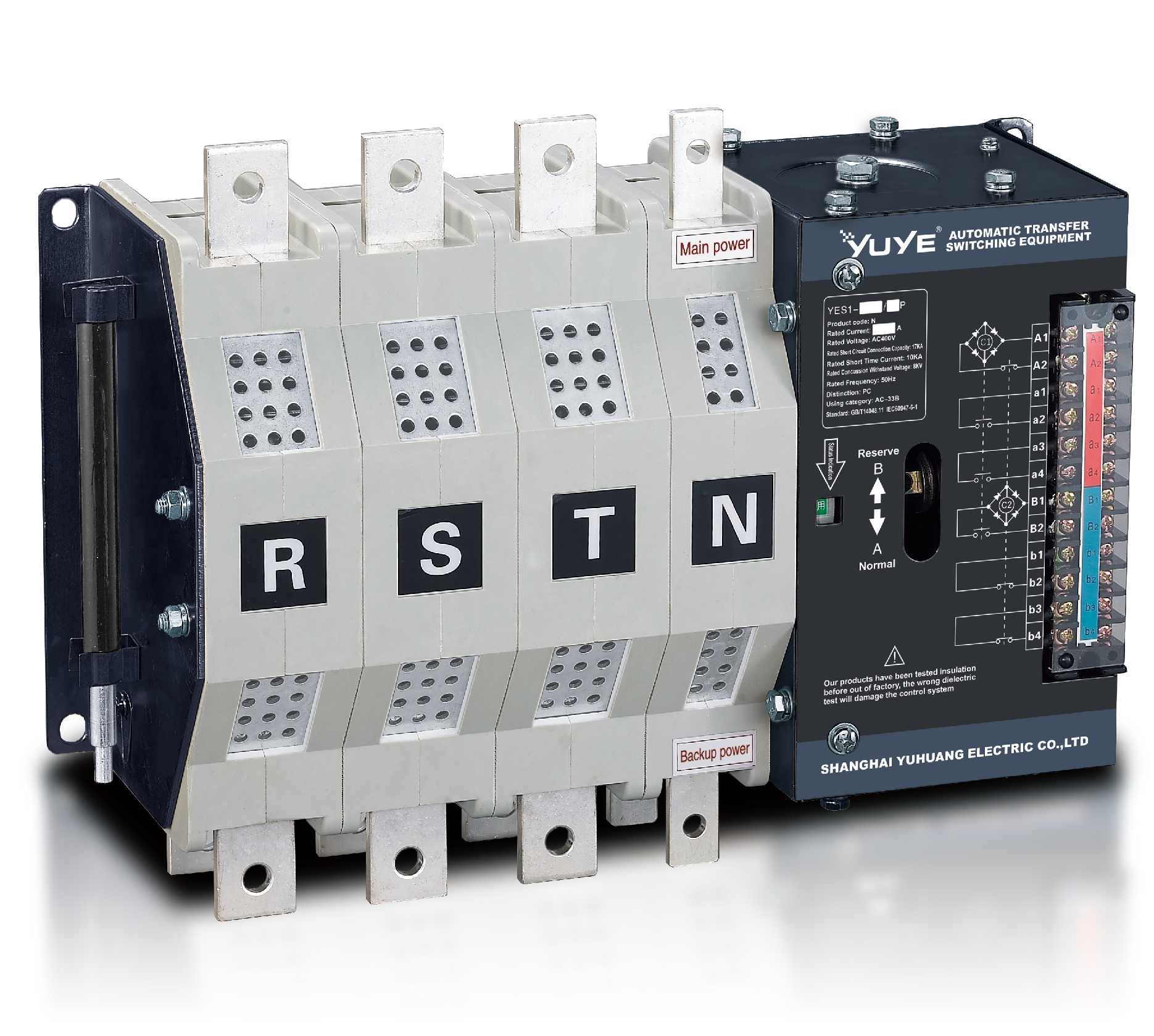 Solenoid-type ATS YES1-250~630N/NT
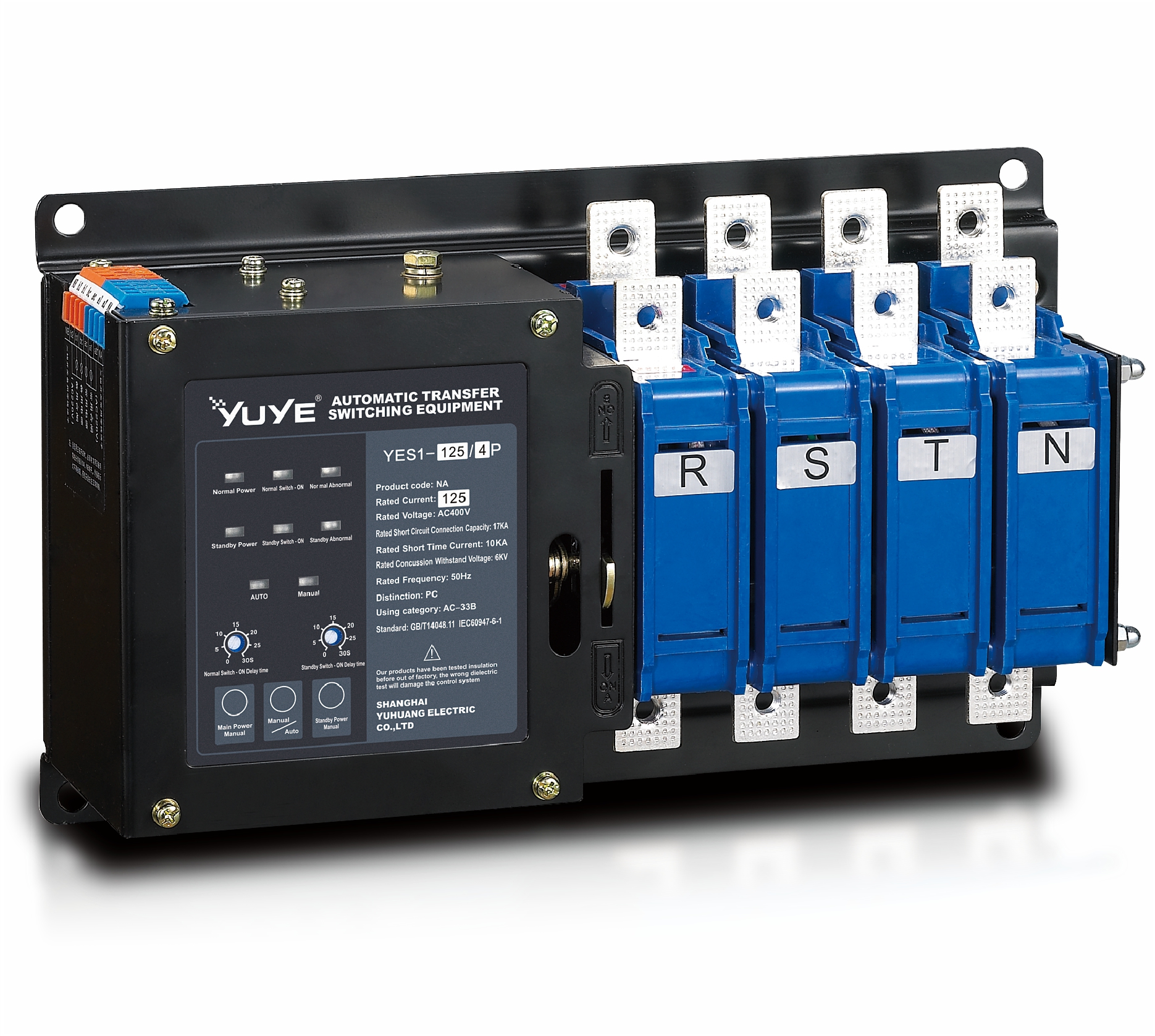 Solenoid-type ATS YES1-32~125NA
 Solenoid-type ATS YES1-63~630SN
 Solenoid-type ATS YES1-1250~4000SN
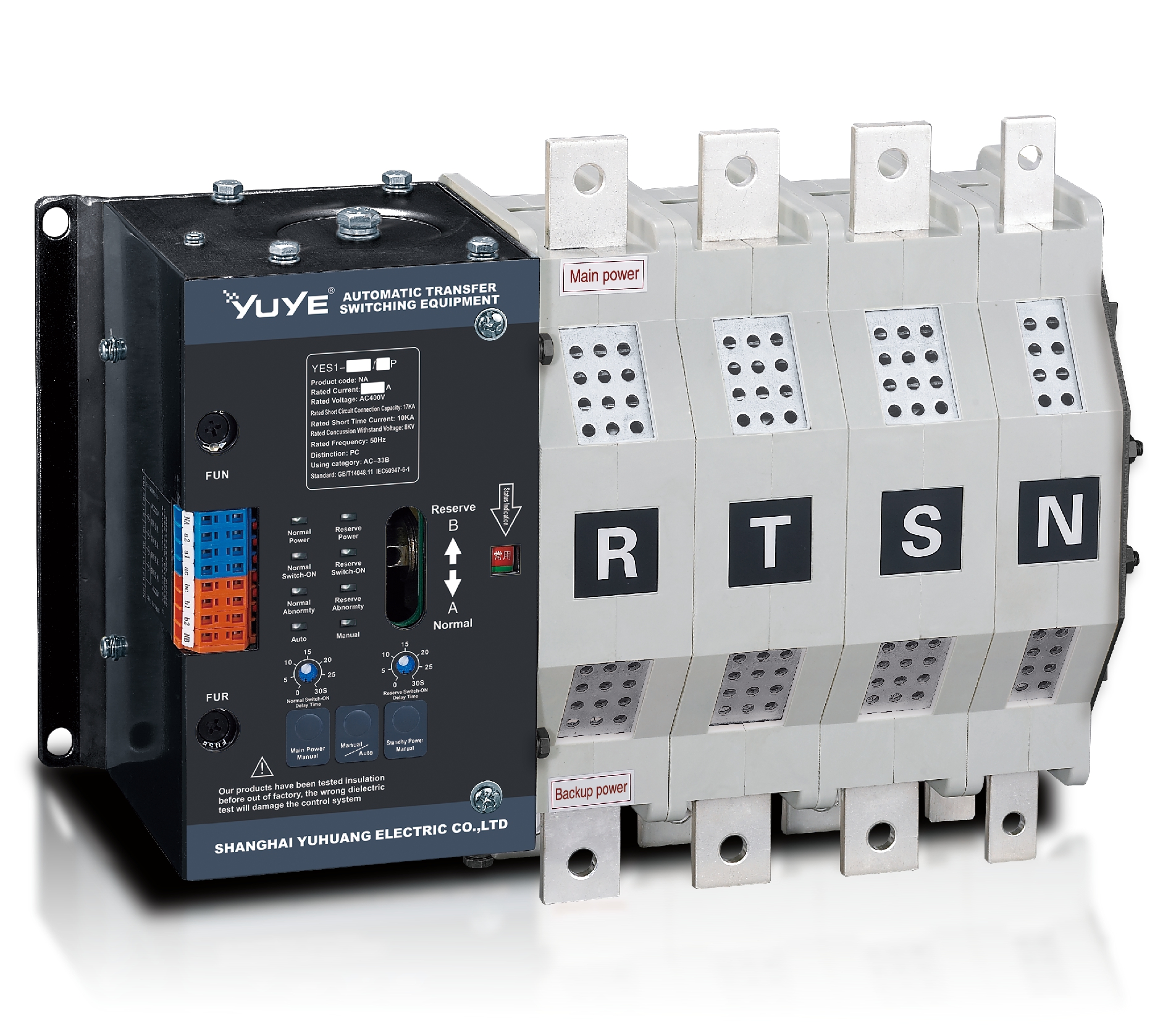 Solenoid-type ATS YES1-250~630NA/NAT
 Solenoid-type ATS YES1-63NJT
 PC ATS YES1-100~1600GN1/GN/GNF
 PC ATS YES1-2000~3200GN/GNF
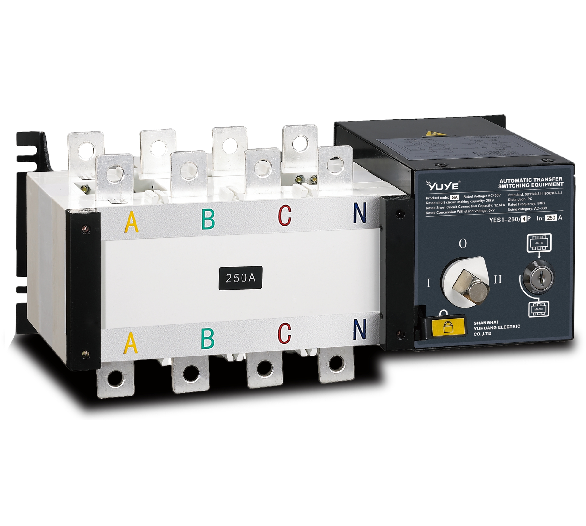 PC ATS YES1-100~3200GA1/GA
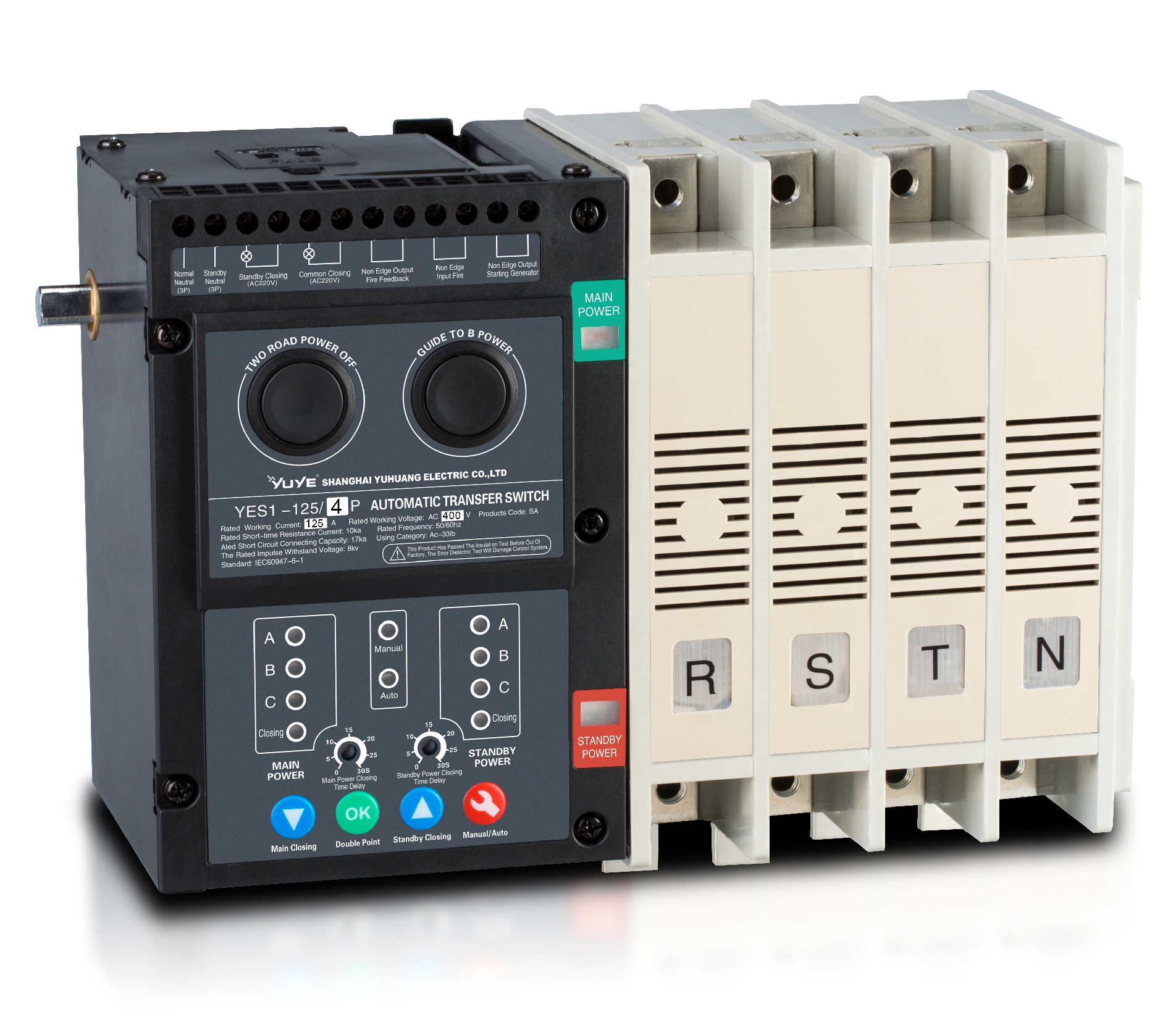 Solenoid-type ATS YES1-63~630SA
 Solenoid-type ATS YES1-63~630L/LA
 Solenoid-type ATS YES1-63~630LA3
 Solenoid-type ATS YES1-63MA
 PC ATS YES1-630~1600M
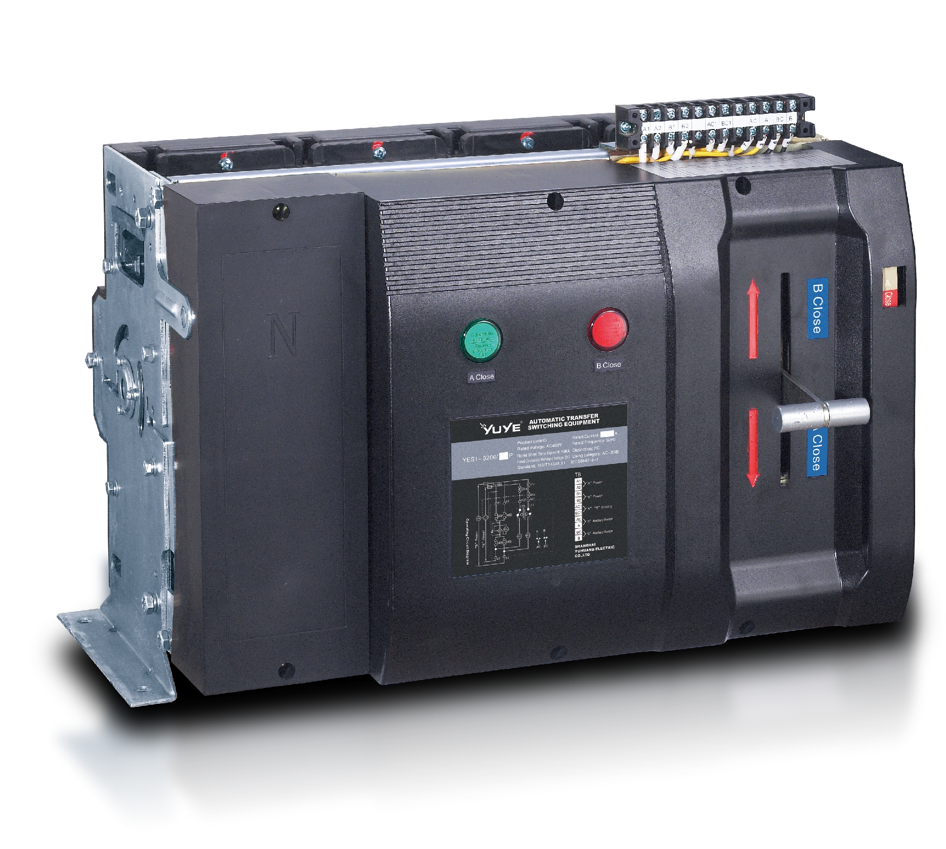 PC ATS YES1-3200Q
 Solenoid-type ATS YES1-4000~6300Q
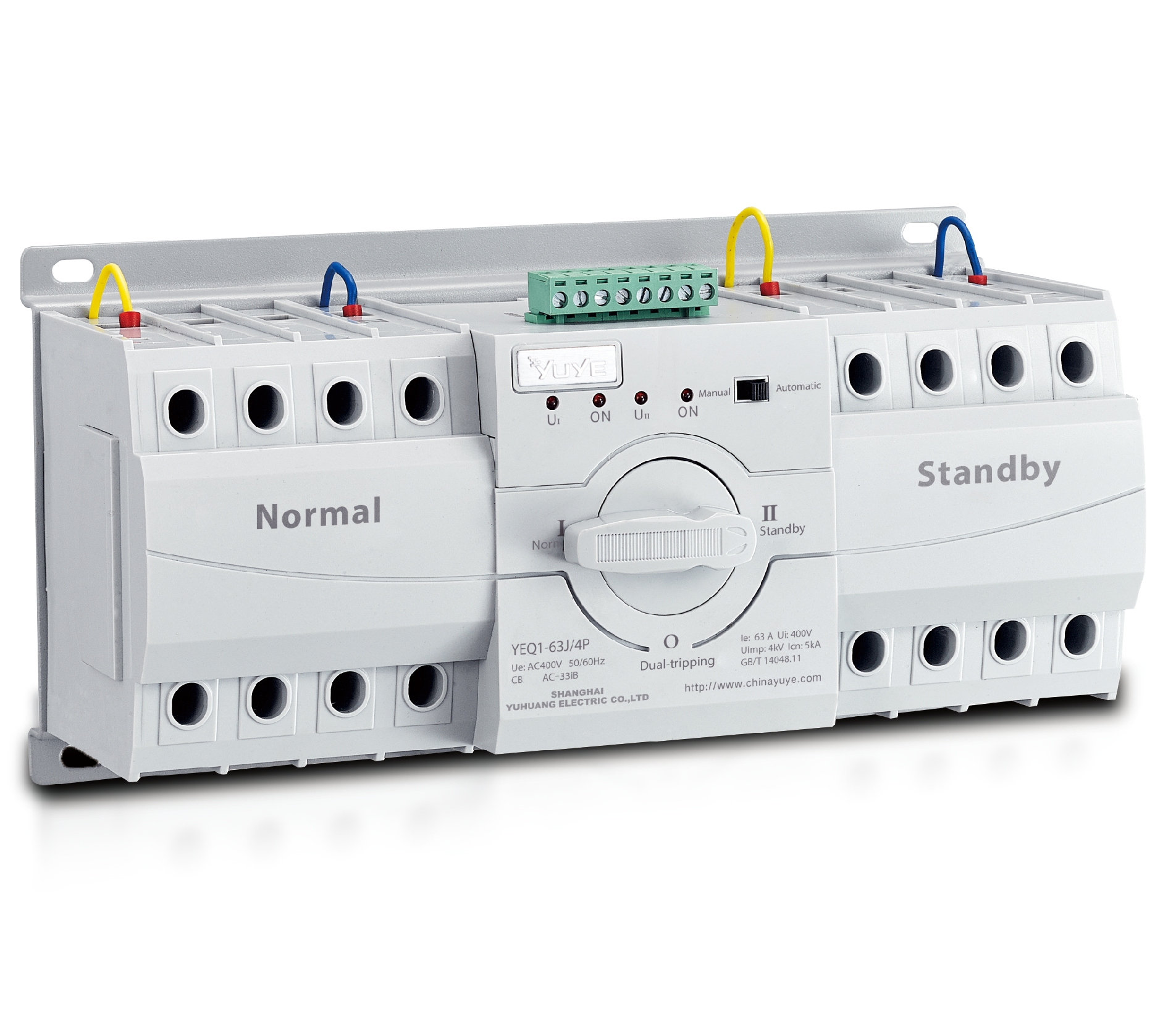 CB ATS YEQ1-63J
 CB ATS YEQ2Y-63
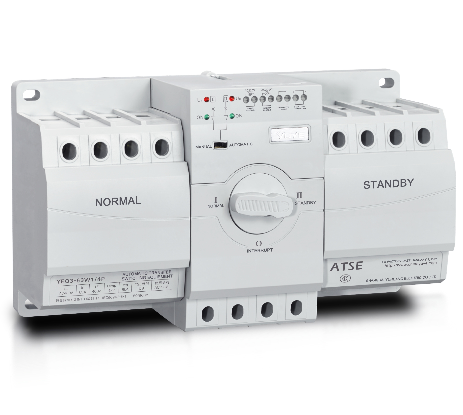 CB ATS YEQ3-63W1
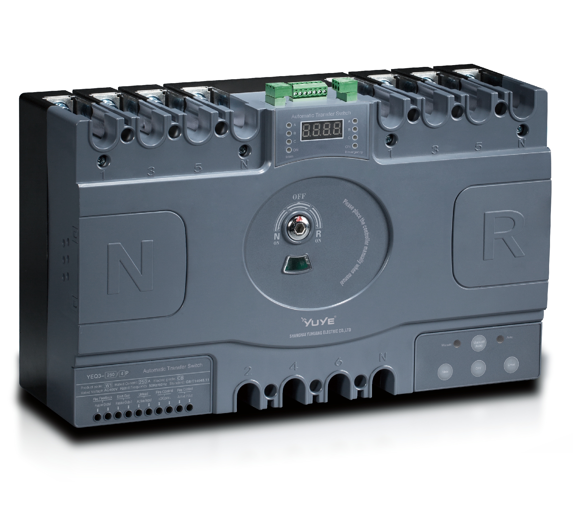 CB ATS YEQ3-125~630W1
 ATS controller Y-700
 ATS Controller Y-700N
 ATS Controller Y-701B
 ATS Controller Y-703N
 ATS Controller Y-800
 ATS Controller W2/W3 Series
 ATS switch Cabinet floor-to-ceiling
 ATS switch cabinet
 JXF-225A power Cbinet
 JXF-800A power Cbinet
 YEM3-125~800 Plastic Shell Type MCCB
 YEM3L-125~630 Leakage Type MCCB
 YEM3Z-125~800 Adjustable Type MCCB
 YEM1-63~1250 Plastic Shell Type MCCB
 YEM1E-100~800 Electronic Type MCCB
 YEM1L-100~630 Leakage Type MCCB
 Air Circuit Breaker YEW1-2000~6300
 Air Circuit Breaker YEW3-1600
 Miniature circuit breaker YEMA2-6~100
 Miniature circuit breaker YEB1-3~63
 Miniature circuit breaker YEB1LE-3~63
 Miniature circuit breaker YEPN-3~32
 Miniature circuit breaker YEPNLE-3~32
 Miniature circuit breaker YENC-63~125
 Load isolation switch YGL-63~3150
 Load Isolation Switch YGL2-63~3150
 DC relay YDC-P20
 DC relay YDC-P250
 DC relay YDC-P400
 DC relay MDC-300M
 DC relay YDC-M400
 DC Isolation Switch YEGL3D-630
 YECPS2-45~125 LCD
 YECPS-45~125 Digital
 CNC Milling/Turning-OEM
When the grid goes down, the real question is not whether you have a backup source — it is how to connect that source without endangering the people working on the lines. A manual transfer switch answers that question with mechanical certainty: one handle, two positions, and an interlock that makes simultaneous connection physically impossible.
What Is a Manual Transfer Switch?
A manual transfer switch is a switch-disconnector with two inputs — UTILITY and GENERATOR — and one output feeding the load. The operator selects the active source by moving a handle. There is no sensing circuit, no controller, and no automatic actuation.
The safety-critical part is the mechanical interlock: a pinned linkage that blocks the handle from reaching the second position while the first is closed. This is what prevents backfeeding the utility, rather than merely discouraging it. Switching is break-before-make, so the two sources are never paralleled.
Manual vs. automatic. An ATS adds voltage sensing and a motor or solenoid, transferring in seconds and without an operator on site. A manual unit costs far less, has almost no failure modes, and still works after a decade of sitting idle. If someone is present during an outage — a home, a workshop, a farm — the manual switch is usually the better engineering decision. If the load cannot tolerate minutes of outage, you need an ATS.
Types and Configurations
By poles. Two-pole units switch both ungrounded conductors in 120/240 V single-phase systems, with a solid neutral — the standard residential choice. Three-pole units serve three-phase systems where the neutral is not switched. Four-pole units switch all three phases plus neutral, and are required when the generator is a separately derived system with its own neutral-to-ground bond. Leaving the neutral solid in that case creates a parallel neutral path between grounding electrodes, which carries objectionable current and trips RCDs.
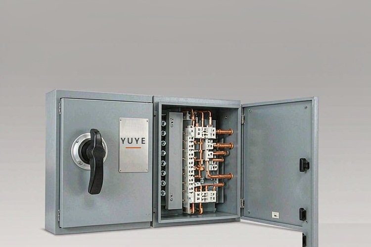
By mounting. Panel-mounted (open type) units sit inside an existing cabinet. Enclosed units come in their own NEMA-rated box, wall-mounted beside the service — the most common format for residential and light commercial work. Service-entrance rated units carry the short-circuit rating and disconnect function needed at the service.
By mechanism. Rotary cam switches are compact with positive break-before-make action. Knife-blade double-throw switches show a visible air gap. Linked contactor pairs handle higher currents where a single rotary element becomes impractical.
How to Size a Manual Transfer Switch
Four numbers decide the model: continuous current, voltage, poles, and short-circuit withstand.
- Build the load list for the circuits you actually intend to back up — not the whole panel. Motor loads draw three to six times running current at start, and that surge often governs the rating.
- Calculate current. Single phase: I = P ÷ (V × PF). Three phase: I = P ÷ (√3 × V × PF).
- Apply the continuous factor. Multiply by 1.25 and round up to the next standard size.
- Check the short-circuit current rating against the available fault current at the terminals. This is a code requirement and the item most often missed on small projects.
- Derate for conditions. Standard ratings assume roughly 40 °C ambient; a hot mechanical room or a sealed sun-exposed enclosure reduces capacity. Use the manufacturer’s table.
Example. A 10 kW standby load at 240 V draws 41.7 A. With the 1.25 factor, 52 A — specify 60 A, not 50 A. For three phase, 45 kW at 400 V and 0.9 PF draws 72.2 A, becoming 90 A, so specify 100 A.
Also confirm the utilisation category: AC-23 for motor and mixed inductive loads, AC-21 for resistive.
Installation and Wiring
Service-entrance work, grounding, and utility coordination are licensed-trade work. The steps below describe correct practice, not a DIY procedure.
1. Identify the system type. Separately derived or not? This one answer determines 3-pole versus 4-pole and cannot be corrected later by careful wiring.
2. Isolate and verify. Open and lock the main breaker, then prove absence of voltage with a tester you have checked against a known live source.
3. Land the conductors. Utility to UTILITY, generator feeder to GENERATOR, backed-up loads to LOAD. Reversing utility and load energises the panel from the wrong side.
4. Torque to specification. Under-torqued lugs are the leading cause of transfer switch overheating. Use a calibrated wrench.
5. Handle neutral and ground correctly. Never bond neutral and ground at both the service and the generator.
6. Prove the interlock. With the handle at UTILITY, it must be mechanically blocked from GENERATOR, and the reverse. Then cycle the switch several times and test under load for 30 minutes.
Common mistakes: backfeeding through a suicide cord instead of a listed switch; double-bonded neutrals; sizing to the generator rather than the load; ignoring the SCCR; mounting a NEMA 1 enclosure outdoors.
Standards and Maintenance
Specify against IEC 60947-3 for switch-disconnectors, UL 1008 for transfer switch equipment in North America, and NEC Article 702 for optional standby systems. NFPA 110 applies where the load is legally classified as emergency.
Inspect annually: cycle the switch under load, check contacts for pitting, verify lug torque, scan terminations thermographically, and confirm the interlock still blocks both directions. Every three to five years, measure insulation resistance and contact resistance against commissioning values. Replace the unit when contacts are heavily eroded, the interlock has been damaged, or the enclosure can no longer hold its NEMA rating.
FAQ
3-pole or 4-pole?
Four-pole if the generator neutral is bonded at the generator; three-pole with a solid neutral if it is not.
Can it be mounted outdoors?
Yes, with a NEMA 3R enclosure minimum, correct conduit entries, and drip loops.
How fast is the transfer?
As fast as an operator can reach the switch — minutes, not seconds.
Conclusion
A manual transfer switch is deliberately low-tech, and that is its value: a mechanical interlock and a set of contacts that keep working when electronics have failed. Confirm four things before ordering — system type, calculated continuous current, available fault current, and enclosure rating for the actual location. Those four answers determine the model; everything else is accessory selection.
