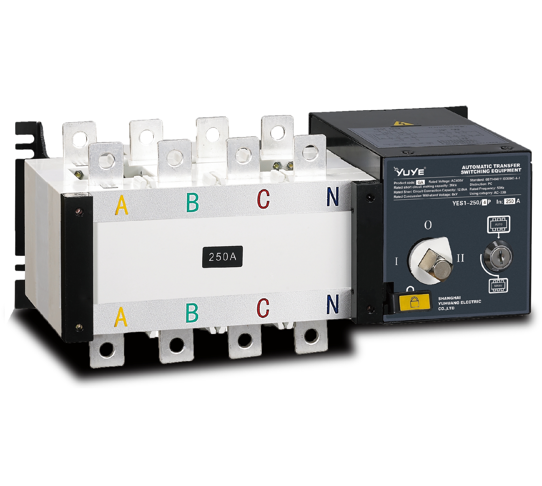
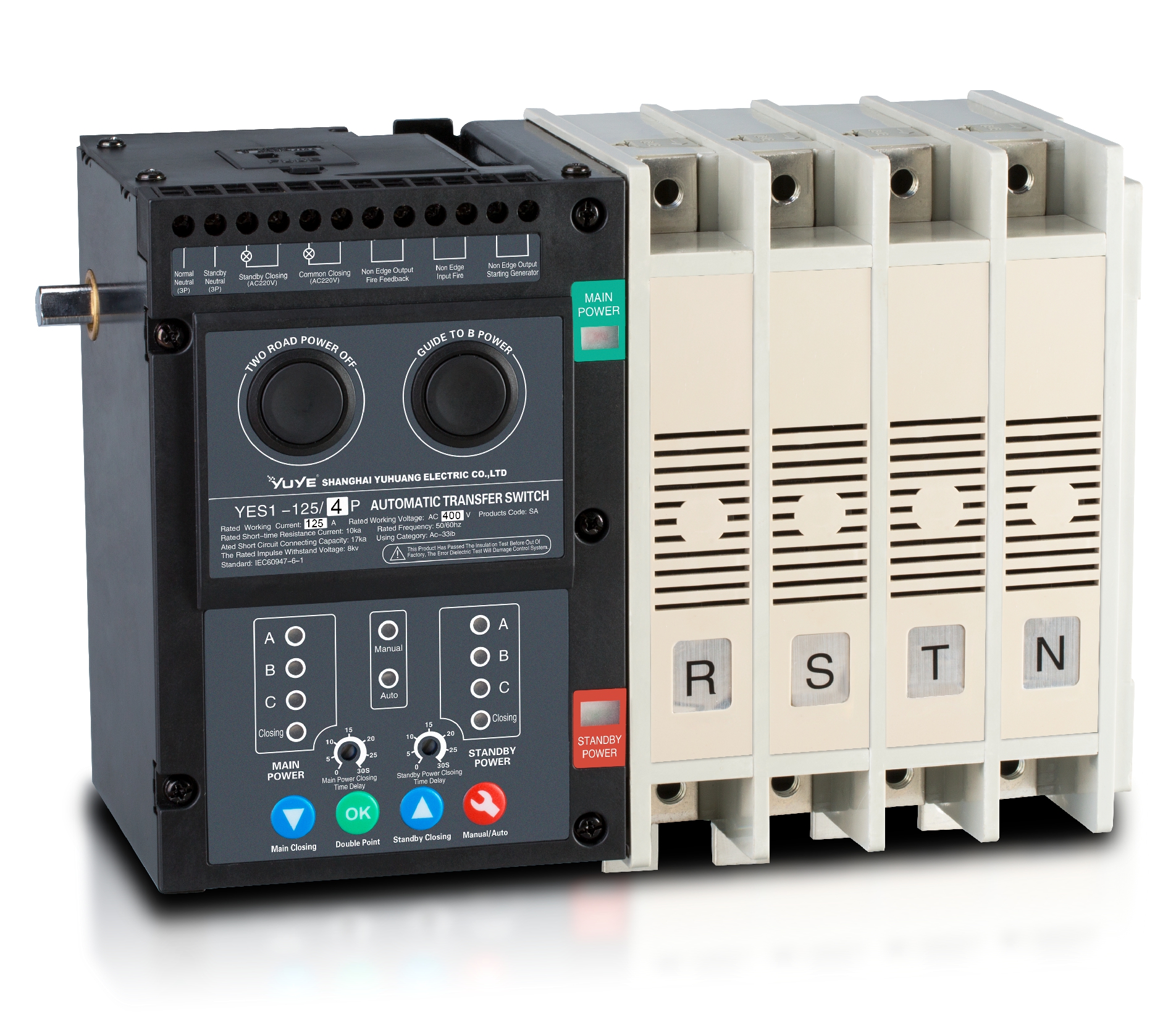
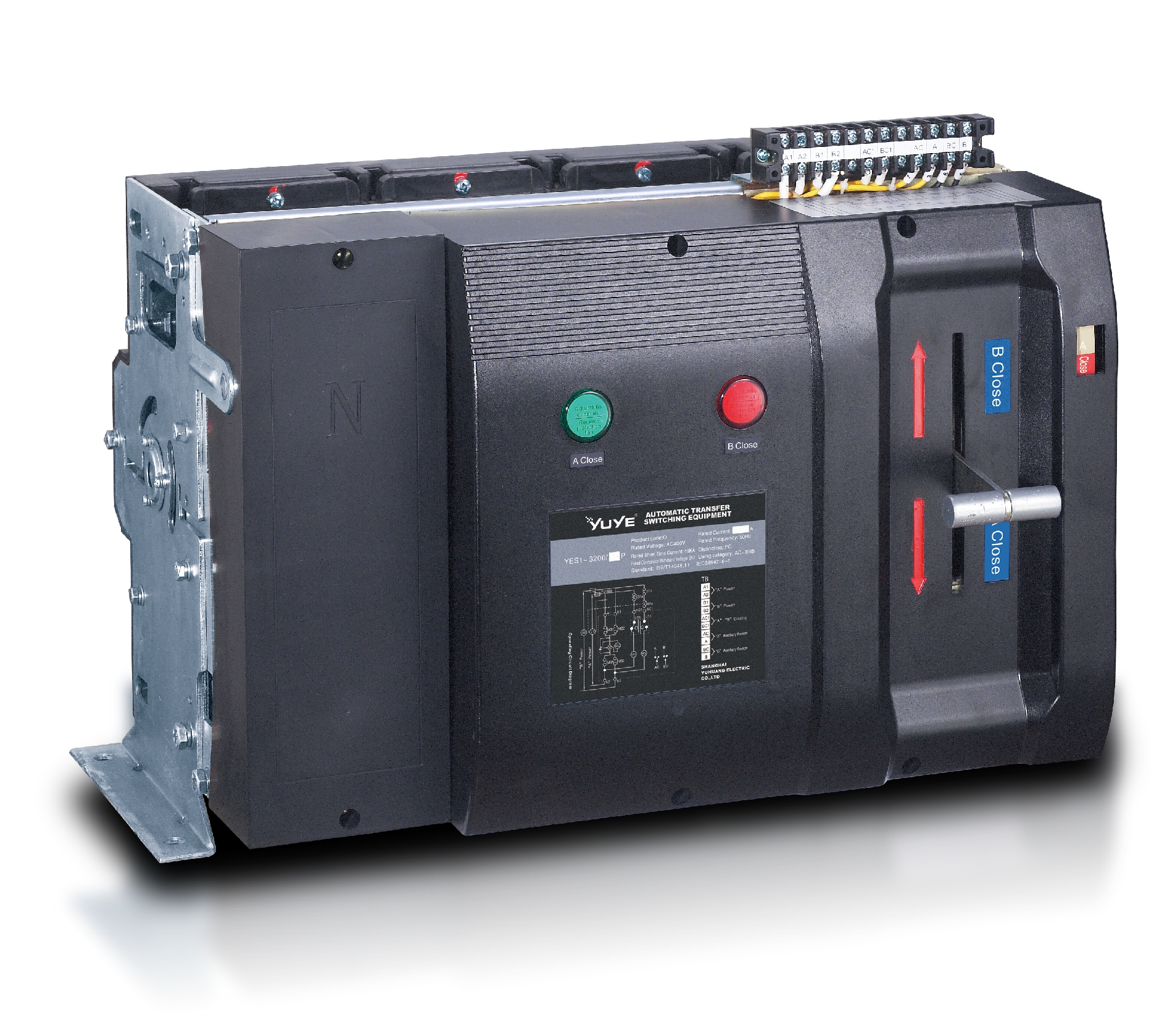
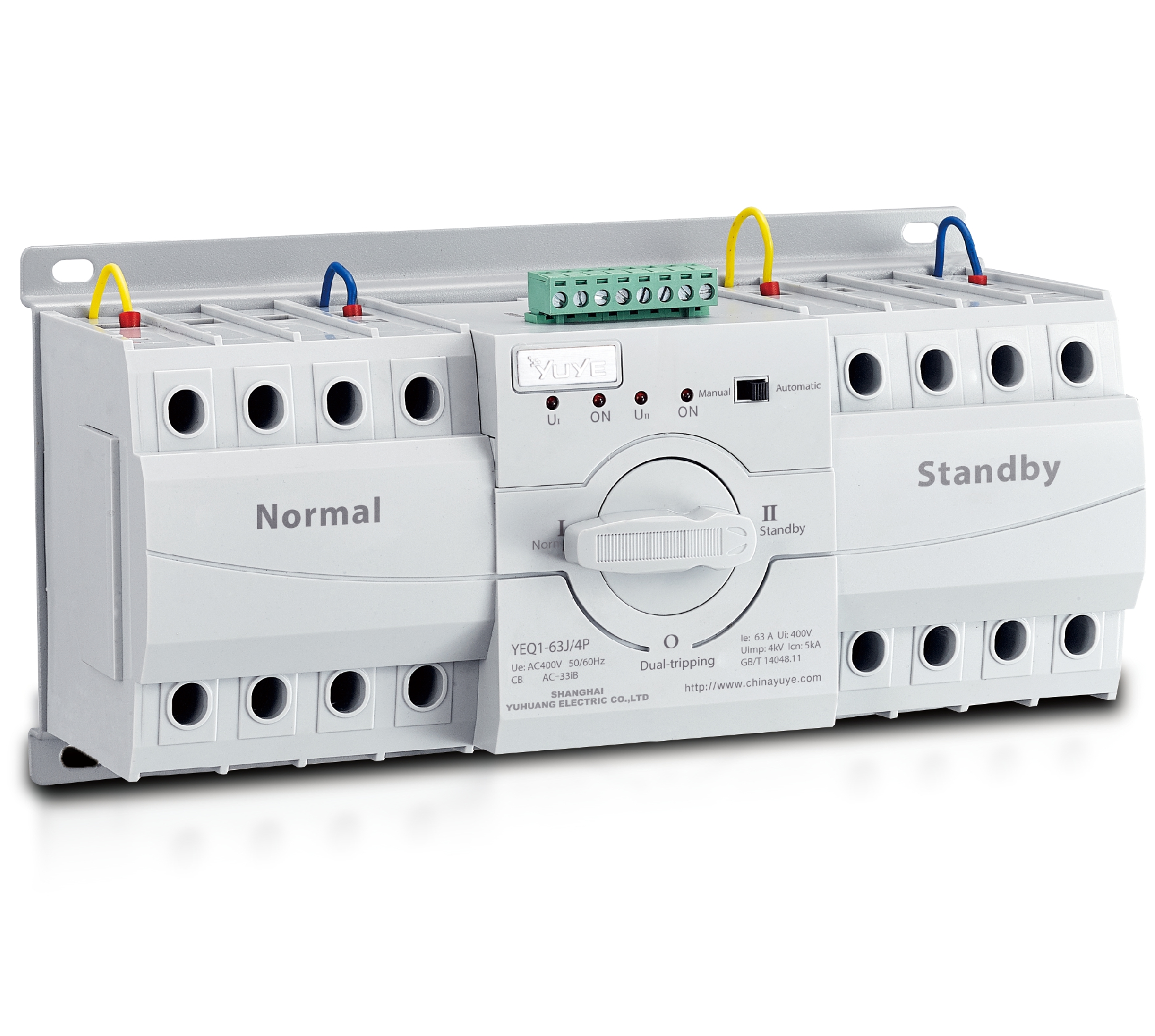
PC ATS YECT1-2000G
PC ATS YES2-63~250GN1
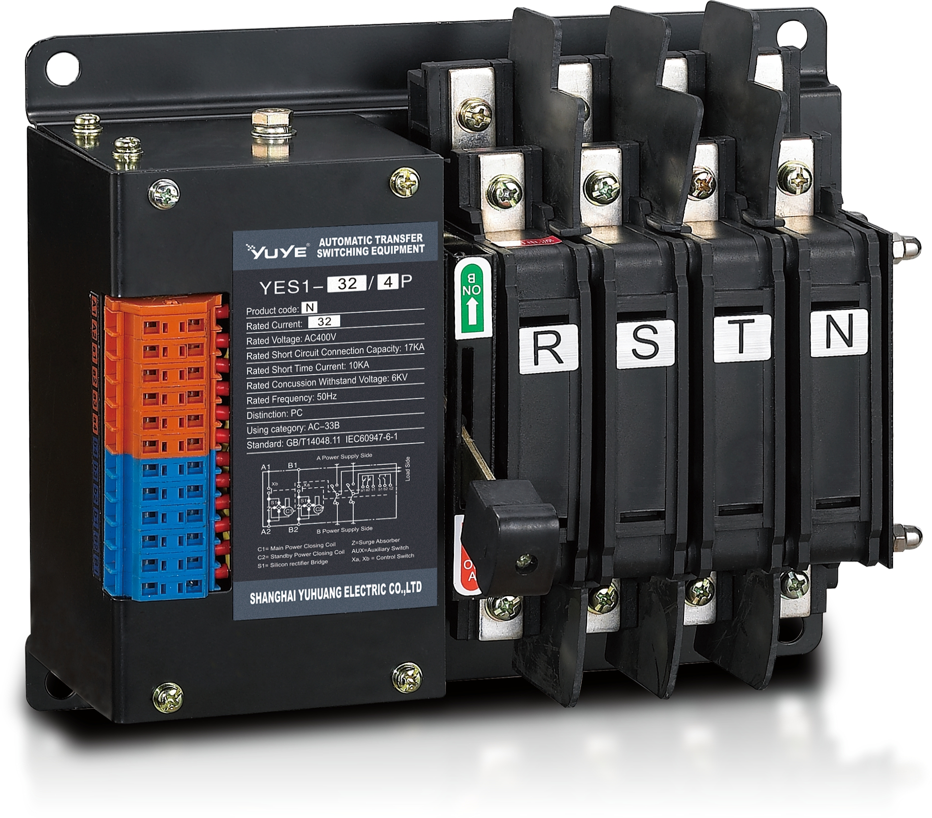
Solenoid-type ATS YES1-32~125N
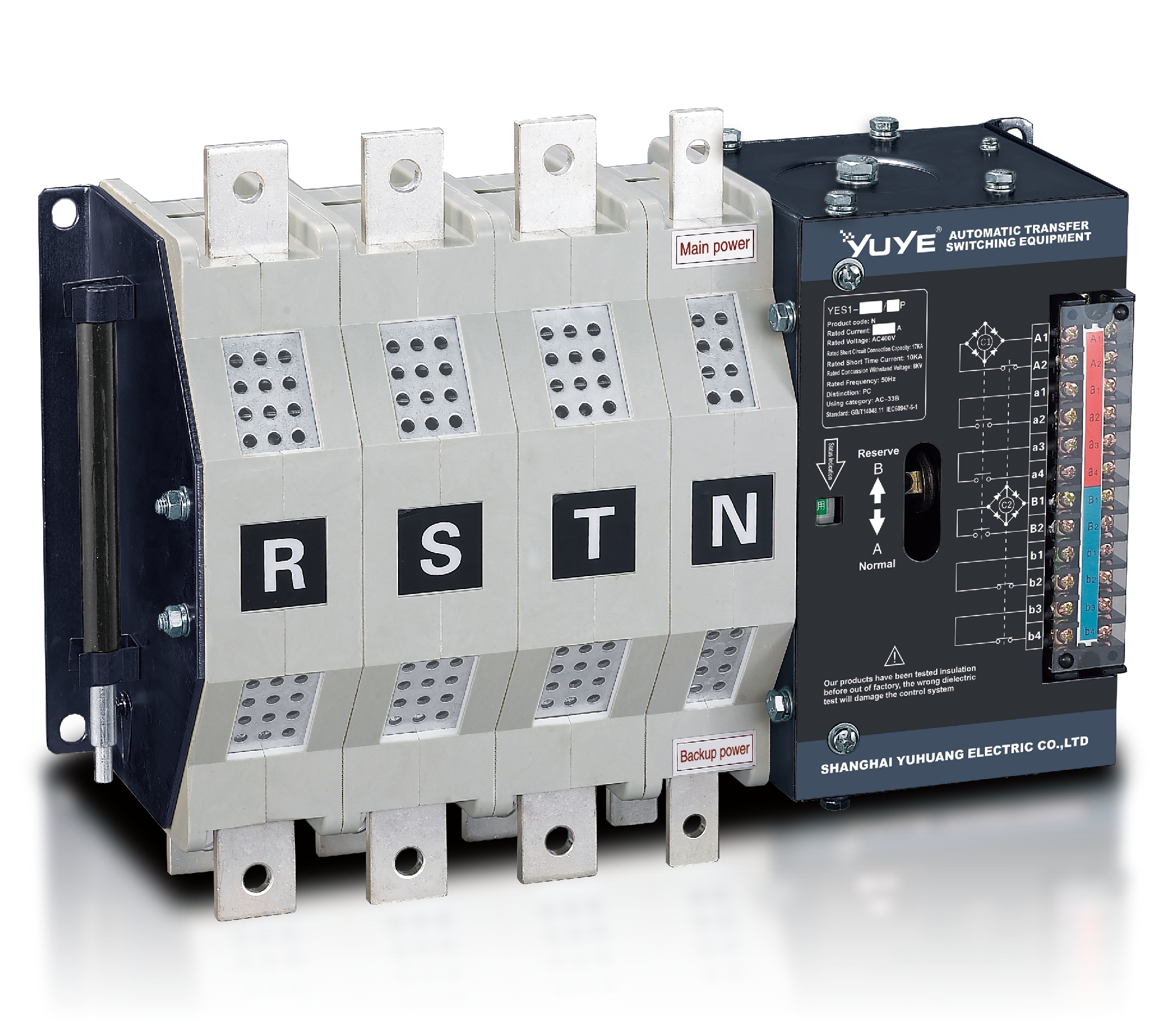
Solenoid-type ATS YES1-250~630N/NT
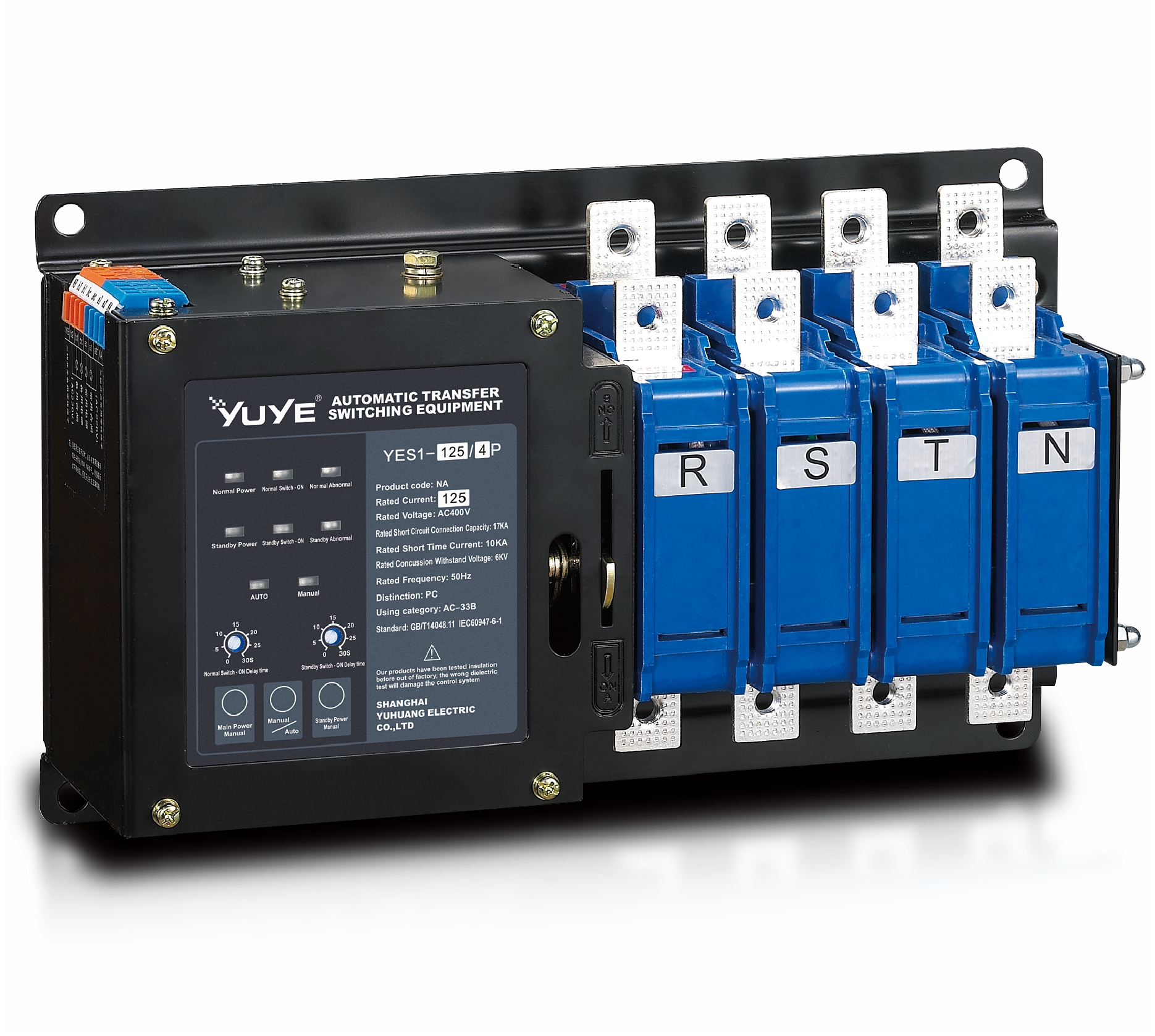
Solenoid-type ATS YES1-32~125NA
Solenoid-type ATS YES1-63~630SN
Solenoid-type ATS YES1-1250~4000SN
Solenoid-type ATS YES1-250~630NA/NAT
Solenoid-type ATS YES1-63NJT
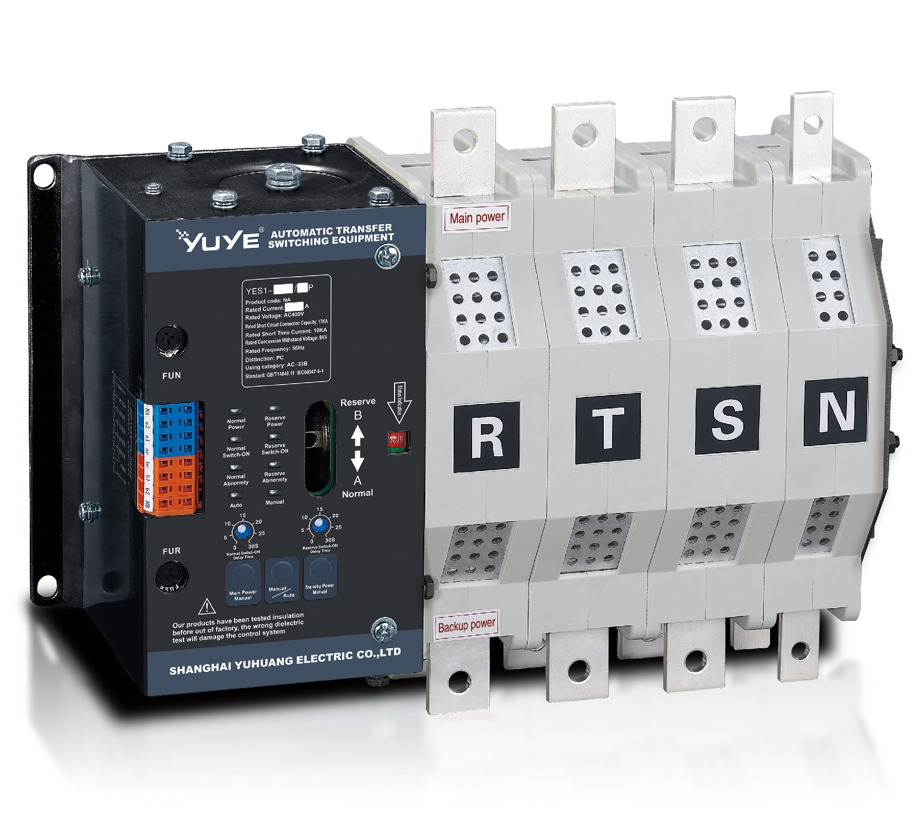
PC ATS YES1-100~1600GN1/GN/GNF
PC ATS YES1-2000~3200GN/GNF
PC ATS YES1-100~3200GA1/GA
Solenoid-type ATS YES1-63~630SA
Solenoid-type ATS YES1-63~630L/LA
Solenoid-type ATS YES1-63~630LA3
Solenoid-type ATS YES1-63MA
PC ATS YES1-630~1600M
PC ATS YES1-3200Q
Solenoid-type ATS YES1-4000~6300Q
CB ATS YEQ1-63J
CB ATS YEQ2Y-63
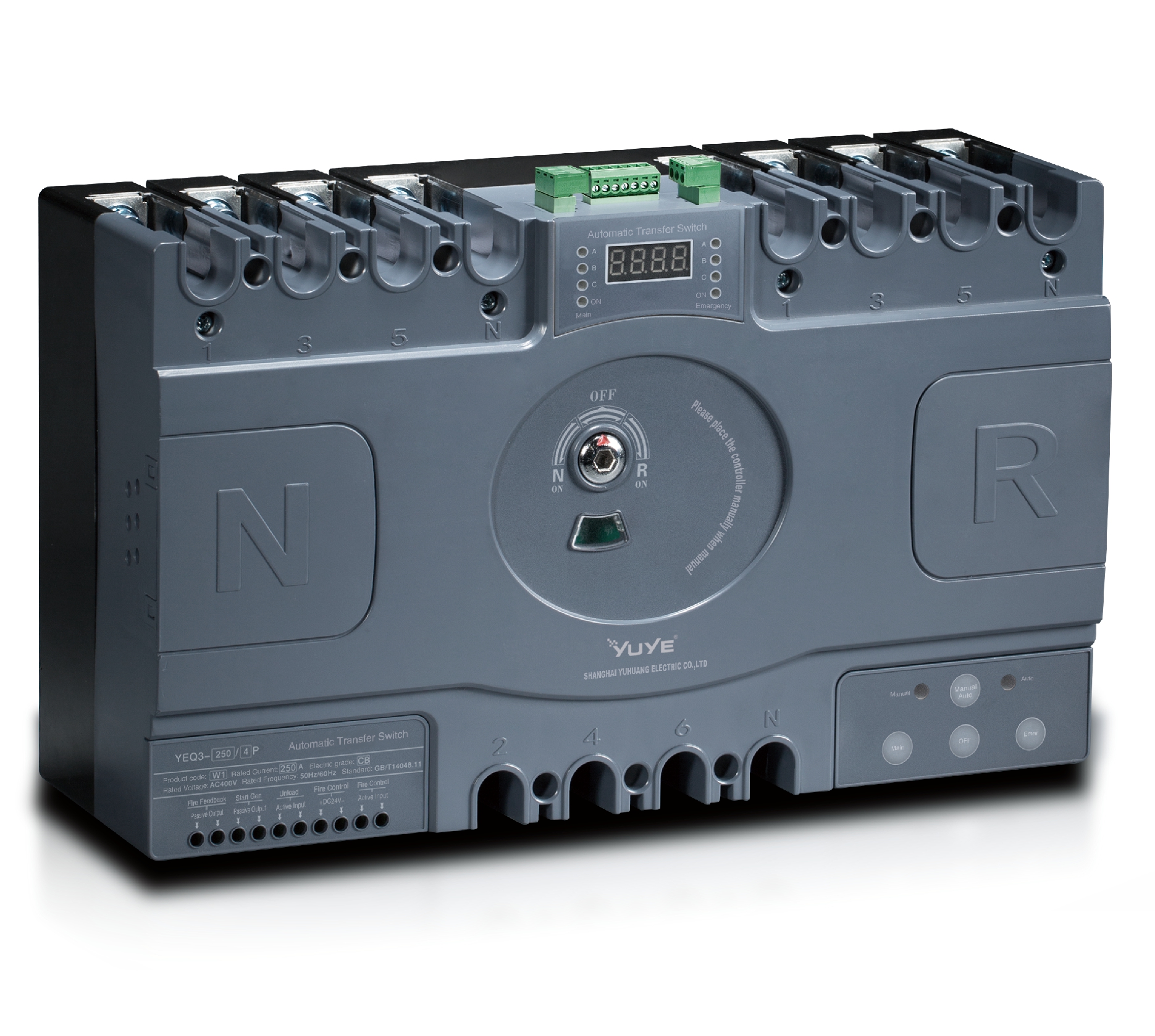
CB ATS YEQ3-63W1
CB ATS YEQ3-125~630W1
ATS controller Y-700
ATS Controller Y-700N
ATS Controller Y-701B
ATS Controller Y-703N
ATS Controller Y-800
ATS Controller W2/W3 Series
ATS switch Cabinet floor-to-ceiling
ATS switch cabinet
JXF-225A power Cbinet
JXF-800A power CbinetPicking the right 63A Automatic Transfer Switch isn’t just about matching a current rating. You gotta consider whether it fits your generator, the load it’s intended for, fault levels, the enclosure, and where you’re installing it. For example, a 63-amp switch might work just fine for a small commercial panel, a telecom cabinet, a clinic circuit, or a backup system—but watch out! If you’ve got a motor load that kicks off with a lot of inrush current, it could cause problems.
Industry reports really drive home why this stuff matters. Grand View Research points out that demand for these switches is climbing in data centers, hospitals, and big commercial buildings. And the Uptime Institute’s Global Data Center Survey keeps highlighting power outages as a major risk—so, it’s pretty clear that reliability depends on more than just the product name on the box. It’s all about how you design the system.
Pay attention to the little things. Honestly, reliability starts with really understanding your application—not just blindly picking a rating. Take Michael Chastain from Eaton, for example—he emphasizes that the key is to review everything thoroughly: switching capacity, short-circuit ratings, transition type, phase setup, controller features, and bypass options. Make sure the source voltages match what’s on your equipment’s label, and don’t forget to check the neutral configuration.
The NFPA 110 standard from the National Fire Protection Association really stresses the importance of reliable emergency and standby power systems. Following their guidelines can influence your installation, testing, and maintenance plans. But here’s the catch—just because something looks good on paper doesn’t mean it’s enough. A neat spreadsheet with specs can be misleading if you don’t really know how the load will behave in real life.
So, always measure the load. Think about your generator’s starting power, the ambient temperature, available space, and how easy it’ll be to perform maintenance. Then, compare that info with tested data from trusted manufacturers like Eaton, Schneider Electric, or ABB. Remember, the most expensive or feature-packed switch isn’t always the best choice. What really matters is finding one that performs reliably when the main power goes out—that’s what counts.
A 63A automatic transfer switch monitors two power sources and changes supply when the primary source fails. Its role is not simply to “move electricity.” It helps maintain power for lighting, pumps, control panels, and other essential loads. The switch detects voltage loss, unstable frequency, or phase problems, depending on its design. It then starts a generator or transfers the load to an available source. Timing matters. A delayed transfer can interrupt sensitive equipment, while a rushed transfer may create unnecessary stress.
The 63A rating describes the continuous current the switch can carry under specified conditions. It does not automatically suit every 63A installation. Electricians should check the actual load, motor starting current, ambient temperature, enclosure rating, and available fault current. Neutral switching also deserves attention, especially where generators use separate grounding arrangements. In practical inspections, the label is often trusted too quickly. That is a mistake worth reconsidering.
Tips: Measure real operating current, not only the panel rating. Check whether the load includes motors, heaters, or electronic power supplies. Confirm transfer and retransfer delays with a controlled test. Inspect terminals for heat marks after commissioning. Keep written test records. A qualified electrician should verify conductor sizing, protection settings, and local installation requirements before energizing the system. Do not test by casually disconnecting live equipment. Simulated failures are safer and more repeatable.
Choosing a 63A automatic transfer switch starts with the power supply and load, not the rating label. Record source voltage, phase, frequency, neutral arrangement, and available short-circuit current. A 63A switch may support different capacities under different installation conditions.
Measure twice. Do not guess.
Calculate the actual load, including motors, compressors, heaters, and electronic equipment. Starting current can briefly exceed running current several times. Check continuous loading, ambient temperature, cable size, and enclosure ventilation. For three-phase systems, confirm whether the load is balanced. An uneven neutral current can create heat and nuisance transfers. IEC 60947-6-1 provides a useful reference for transfer switching equipment requirements.
Reliability matters when the load supports critical operations. The International Energy Agency reported that data centres consumed about 415 TWh of electricity in 2024, showing how quickly power infrastructure is becoming more demanding.
Uptime Institute’s 2024 outage analysis found that more than half of surveyed operators experienced an outage within three years. These figures do not make every installation critical, but they justify careful source verification and testing.
In practice, simulate a source failure before approval. Confirm transfer delay, generator compatibility, phase rotation, bypass needs, and restart behavior. A failed test is valuable. It reveals assumptions while the system is still safe to correct. Select the 63A model only after comparing calculated demand with its rated operational category and the installation’s protection settings.
Choosing a 63A automatic transfer switch starts with the transfer type, not the enclosure.
Open-transition switches briefly disconnect the load before connecting the alternate source. They suit most generator systems, but sensitive equipment may restart.
Closed-transition models overlap sources momentarily, reducing interruption. They require coordinated protection and utility approval.
Delayed-transition designs add a programmed pause, useful for large motor loads and residual voltage.
Operating mode matters equally. Automatic mode detects source failure and transfers without operator action. Manual mode supports maintenance, testing, or control-system failure. Test mode should simulate a source loss without unnecessarily interrupting critical circuits.
Uptime Institute’s 2023 Annual Outage Analysis identified power-related faults in 44% of reported incidents. That figure makes source monitoring and transfer reliability practical priorities, not paperwork.
Tips: Confirm continuous current, motor inrush, pole configuration, neutral switching, short-circuit withstand, and generator compatibility. Check whether the 63A rating applies to the full enclosure temperature range.
I would not trust a catalog rating alone. Field wiring, ambient heat, and poor coordination can change performance. Keep it practical. Record transfer times during commissioning, then repeat the test under realistic load. A clean test result is useful, but it is not permanent proof. Recheck after major load changes.
Choosing a 63A automatic transfer switch starts with voltage, not amperage. Confirm the supply and backup ratings match, such as 230V single-phase or 400V three-phase. The switch must also match the system frequency. The U.S. Energy Information Administration identifies 60 Hz as the standard frequency across U.S. power systems. Many other markets use 50 Hz.
Phase selection matters. A single-phase switch cannot safely replace a three-phase unit. Pole configuration needs equal attention. Two-pole equipment may switch line conductors, while four-pole equipment can also isolate the neutral. Follow the grounding design and local electrical rules. IEC 60947-6-1 evaluates transfer switching equipment by rated voltage, current, and utilization category. A 63A label alone proves very little. Motor starting current, heater loads, and generator capacity can exceed normal running demand. This is where a tidy specification can still fail.
Tips: Record voltage, phase, frequency, neutral arrangement, and load type before ordering. Compare the switch’s rated operational current with measured demand, not only the main breaker size. The U.S. Department of Energy recommends accounting for starting loads when sizing backup power systems. Check terminal size and enclosure conditions too. Heat matters. Finally, ask a qualified electrician to verify compatibility on site. Manuals are helpful, but they can be incomplete for older installations.
How to Choose the Right Automatic Transfer Switch 63A
A 63A automatic transfer switch must protect people, equipment, and continuity of power. Check for mechanical and electrical interlocking before reviewing appearance. These features prevent both sources from connecting accidentally. Break-before-make switching is usually safer for standard installations. Confirm whether the neutral is switched, especially with separately derived sources. The switch should also match the system voltage, frequency, fault current, and load type. A 63A rating alone does not prove suitability.
Certification needs careful checking. Look for test standards relevant to transfer switching, such as IEC 60947-6-1 or applicable regional requirements. The certification should cover the complete assembly, not only internal components. Ask for test reports, temperature-rise data, and clear installation limits. Documents can be incomplete. That is worth questioning. A qualified electrician should verify coordination with upstream protection, because the transfer switch is not a substitute for overcurrent protection.
Tips: Inspect the enclosure rating against the actual location. An IP rating helps indicate resistance to dust and water, while a NEMA rating may describe broader enclosure performance. Indoor electrical rooms may need less protection than outdoor cabinets exposed to rain, sunlight, and condensation. Check cable-entry seals, door gaskets, ventilation, and corrosion resistance. Leave working space around the cabinet. Small installation details often decide whether a reliable switch performs poorly. Recheck the rating after adding accessories, because heat and reduced airflow can change the result.
| Evaluation Criterion | Minimum Acceptable Specification | Preferred Specification for a 63A Installation | What to Verify Before Purchase | Selection Importance |
|---|---|---|---|---|
| Continuous current rating | At least 63 A at the intended system voltage, frequency, and utilization category. | 63 A continuous rating with documented derating information for ambient temperature and installation method. | Check the product nameplate, technical data sheet, terminal rating, and temperature-rise test information. | High |
| Number of poles | Match the supply system: 2-pole for single-phase line switching or 4-pole for a three-phase system where the neutral must also be switched. | Use a mechanically linked switching arrangement with clearly identified line, load, and neutral terminals. | Confirm the wiring diagram and verify whether the neutral is solid, switched, or separately isolated as required by the system design. | High |
| Transfer mechanism | Electrically operated, mechanically held transfer mechanism with positive positioning. | Stable source-to-source transfer with mechanical interlocking that prevents both sources from being connected simultaneously. | Review the internal schematic, interlock description, and transfer-time specification. | High |
| Source monitoring | Detection of loss of voltage on the preferred source before starting a transfer sequence. | Monitoring of undervoltage, phase loss, phase sequence, and frequency where applicable. | Check adjustable pickup/dropout thresholds, phase-monitoring functions, and the controller manual. | High |
| Transfer and retransfer delay | Adjustable time delays to reduce nuisance transfers caused by short voltage dips. | Separate adjustable delays for engine start, transfer, emergency-source stabilization, and retransfer. | Verify the adjustment ranges, time-delay accuracy, and whether settings are protected against unauthorized changes. | High |
| Manual operation | Manual test or manual transfer function that does not defeat source interlocking. | Lockable manual control with clear position indication and a documented emergency operating procedure. | Inspect the operating handle, key interlock provisions, position indicator, and maintenance instructions. | Medium |
| Short-circuit withstand and protection | Short-circuit withstand rating suitable for the available fault current at the installation point. | Withstand rating coordinated with the upstream protective device and supported by a recognized test report. | Compare the marked short-circuit current rating with the calculated prospective fault current and upstream breaker or fuse data. | High |
| Electrical clearances and insulation | Construction suitable for the rated voltage and pollution level of the installation environment. | Touch-safe barriers, insulated terminals, creepage and clearance values documented for the applicable voltage category. | Review construction drawings, terminal guards, insulation data, and the applicable product safety standard. | High |
| Certification and conformity | Certification or conformity assessment to the standards required by the installation jurisdiction. | Evidence of evaluation to the applicable automatic transfer switch product standard, such as IEC 60947-6-1 or UL 1008 where applicable. | Request a current certificate, listing file, declaration of conformity, and the exact model or configuration covered. | High |
| Ingress protection | Enclosure rating appropriate to the location; IP20 or higher only for clean, restricted indoor electrical areas. | IP54 for general indoor industrial areas with dust or water splashing; IP65 or higher for exposed or washdown-prone locations when specified by the design. | Confirm the IP code under IEC 60529 or the applicable NEMA enclosure designation, including door, gland, and conduit-entry conditions. | High |
| Environmental temperature | Operating temperature range covers the actual installation environment. | Documented operation at approximately −20 °C to +40 °C, with derating or heating provisions where required. | Check the manufacturer’s environmental ratings, controller limits, humidity restrictions, and required ventilation clearances. | Medium |
| Control power compatibility | Control voltage compatible with the available source or dedicated control supply. | Clearly separated control and power circuits, with overcurrent protection and surge protection for the controller where appropriate. | Verify control voltage, tolerances, control-circuit fuse requirements, and wiring-terminal identification. | High |
| Status indication and alarms | Visual indication of normal source, emergency source, and transfer position. | Auxiliary contacts or communication outputs for source availability, common alarm, and switch position. | Check indicator labels, contact ratings, terminal assignments, alarm behavior, and compatibility with the monitoring system. | Medium |
| Maintenance and testing | Accessible terminals and documented periodic test procedure. | Front-accessible controls, replaceable control components where permitted, event history, and a safe test mode. | Review the installation and maintenance manual, recommended inspection interval, and replacement-parts information. | Medium |
| Installation space and cable entry | Enclosure provides adequate bending space and termination capacity for the selected 63A conductors. | Removable gland plates, clearly marked entry points, earth-bonding provisions, and adequate ventilation without reducing the enclosure rating. | Compare enclosure dimensions, cable sizes, terminal torque values, gland requirements, and minimum working clearances. | Medium |

How to Choose the Right Automatic Transfer Switch 63A
Selecting a 63A automatic transfer switch starts with installation conditions, not the rating alone. Confirm the load type, fault level, neutral arrangement, and available enclosure space. IEC 60947-6-1 provides the relevant framework for transfer switching equipment. However, field conditions often expose details that drawings miss. Measure cable bending space. Check heat around the cabinet. Leave room for safe inspection.
Installation quality strongly affects maintenance. Use clearly labeled terminals and accessible test points. Confirm the switching sequence before energizing the load. A 2024 Uptime Institute Annual Outage Analysis reported that 54% of outages cost less than 100,000 dollars, while 14% exceeded one million dollars. A poorly tested transfer system can turn a minor supply failure into expensive downtime. That deserves attention.
Choose monitoring that matches the site’s risk. Useful signals include source availability, transfer position, alarm status, voltage, and event history. Remote communication helps, but it cannot replace physical testing. NFPA 70B emphasizes documented electrical maintenance programs and condition-based decisions. Schedule inspections according to duty, environment, and switching frequency. Record every failed test. Small omissions matter.
I would not assume a 63A unit fits every 63A load. Motor starting current, harmonics, and emergency circuits may change the selection. Review real measurements with a qualified electrician. The first design can be wrong. Revising it early is cheaper.
The global automatic transfer switch (ATS) market is gaining momentum as data centers, healthcare facilities, manufacturing plants, and commercial buildings require more reliable power continuity. Fortune Business Insights’ 2024 market analysis indicates steady expansion in ATS demand, supported by data-center construction, distributed energy systems, and stricter power-resilience requirements. Other 2024 industry estimates place the market’s annual growth in the mid-single digits, reflecting continued investment in backup generators, critical infrastructure, and automated power management.
The CB ATS YEQ2Y-63 is designed for low-voltage applications requiring dependable source transfer and straightforward system integration. It operates at AC400V and supports rated currents from 100A to 800A, with 3P and 4P configurations for different distribution architectures. Its motor-driven mechanism enables automatic switching between normal and standby power sources, helping reduce interruption time during supply faults. As a CB-class automatic transfer switch, it is suitable for building distribution, industrial control panels, emergency power systems, and other applications where coordinated circuit protection is required. Compliance with IEC 60947-6-1, together with CE, CB, and CCC certifications, supports its use in projects that prioritize standardized performance, electrical safety, and dependable equipment selection.
It monitors two power sources. When the primary source fails, it transfers power to the available source. It can support lighting, pumps, control panels, and other essential loads.
No. The rating describes continuous current under specified conditions. Actual suitability depends on load type, temperature, cables, enclosure ventilation, and fault current. A rating label can mislead.
Record voltage, phase, frequency, neutral arrangement, and short-circuit current. Measure actual operating current at the panel. Do not rely only on the main breaker size.
Their starting current can exceed running current several times. This brief surge may overload an unsuitable switch. Include pumps, compressors, heaters, and electronic power supplies in calculations.
The switch must match the system voltage and frequency. A single-phase switch cannot replace a three-phase unit safely. Check whether the system uses 230V single-phase or 400V three-phase service.
Two-pole equipment usually switches the line conductors. Four-pole equipment can also isolate the neutral. The correct choice depends on grounding design and local electrical requirements.
Use a controlled, simulated source failure. Confirm transfer delay, retransfer delay, generator response, and restart behavior. Do not casually disconnect live equipment. A failed test is useful.
Inspect terminals for heat marks after operation. Check conductor sizing, protection settings, phase rotation, and enclosure conditions. Keep written test records. I would recheck assumptions before energizing.
Choosing the right Automatic Transfer Switch 63a begins with understanding its role in maintaining a reliable power supply. It automatically transfers electrical loads from a primary source to a backup source when an outage or abnormal condition occurs, helping protect essential equipment and reduce downtime. Before selecting a unit, identify the available power sources, expected load, starting current, and future capacity needs. Then compare suitable transfer switch types and operating modes, such as automatic, manual, open-transition, or closed-transition operation, according to the application.
Electrical compatibility is equally important. Confirm the system voltage, phase configuration, number of poles, frequency, and current rating before installation. Safety features such as overcurrent protection, mechanical or electrical interlocking, clear status indicators, and appropriate certifications should also be evaluated. The enclosure rating must match the installation environment, including indoor, outdoor, dusty, or damp locations. Finally, consider installation space, maintenance access, remote monitoring, testing functions, and service requirements to ensure dependable long-term performance.