Picking out the right generator automatic transfer switch isn’t just about flipping through a catalog—it’s a decision that really impacts the reliability of your generator, emergency power readiness, and how confidently your equipment runs every day. Sometimes, a switch might look perfect on paper, but then fail miserably in real life when faced with heat, dust, vibration, or an unexpected power outage. Those little details? They matter more than you might think.
In this guide, “10 Tips to Choose a Generator Automatic Transfer Switch,” I’m focusing on practical advice. We’ll look at things like voltage, current capacity, phase setup, transfer speed, controller features, enclosure ratings, bypass options, maintenance access, and whether it plays nicely with your generator. Plus, I’ll touch on how your installation experience factors in. Even if a product checks all the technical boxes, it might still cause headaches if the terminals are packed too tight or if maintenance folks can’t reach the controller easily.
Electrical safety expert Mike Holt once said, “Safety is not expensive, it’s priceless.” That’s a truth that applies to every generator transfer switch project. Spending a bit more upfront on a quality switch can save you tons of trouble later—trouble like difficult testing or hunting for rare replacement parts. Always check out the manufacturer’s technical docs, verify ratings with a qualified electrician, and make sure you’re following local install rules before you buy.
Sometimes, it’s the little things that tell you a product’s quality—like clearly marked terminals, easy-to-read indicator lights, manual operation options, or event logs that tell you what happened during an outage. Ask if the switch can connect to your generator controller or building management system; thinking about future needs is smart, too. Today’s office might become a server room tomorrow, after all.
Now, no checklist is perfect. I’ve seen people choose switches just based on amps alone, which is pretty shortsighted. That kind of approach overlooks important stuff like enclosure conditions, maintenance access, and control compatibility. The best buyers don’t just go for shiny specs—they compare how things will actually work in your real-world situation. This article aims to give you a solid starting point for safer, more reliable choices that won’t let you down.

Define ATS Functions: Open, Closed, and Delayed-Transition Switching Modes
Choosing a generator automatic transfer switch starts with its operating behavior, not its cabinet size. Check load rating, number of poles, fault withstand, sensing accuracy, control voltage, enclosure protection, maintenance access, documentation, and test functions. These details often determine whether the switch performs safely during a real outage.
Open-transition switching breaks the normal source before connecting the generator. It is simple, widely understood, and suitable for most loads. However, sensitive equipment may restart or briefly lose power.
Closed-transition switching overlaps both sources for a controlled interval. This can reduce interruption, but it requires proper synchronization, protection settings, and utility approval where applicable. A rushed installation can create unnecessary risk.
Delayed-transition switching inserts a programmed pause between source disconnection and reconnection. That pause allows motors to shed residual voltage and prevents sudden inrush currents. It works well for pumps, air handlers, and larger mechanical loads. Verify the delay range in the field, because the factory setting may not match the building’s response. Keep it simple. I once underestimated how quickly a motor group recovered, so the selected delay needed adjustment after testing. Record transfer time, voltage readings, interlock operation, and simulated outage results. A clean panel is useful, but measured performance matters more.
Verify NFPA 110 Level 1 Transfer Performance Within 10 Seconds
10 Tips to Choose a Generator Automatic Transfer Switch
Verify NFPA 110 Level 1 Transfer Performance Within 10 Seconds
Choosing a generator automatic transfer switch starts with the ten-second requirement. Confirm that the unit is suitable for NFPA 110 Level 1 applications and local electrical rules. Check its continuous current rating, short-circuit rating, and voltage compatibility. The switch must sense utility failure accurately, not react to every brief voltage dip. Review adjustable time delays, because unnecessary delays can threaten critical loads. Confirm that the generator receives a dependable start signal. Test the control wiring under realistic conditions.
Ask whether the switch supports open, closed, or delayed transition when the facility requires it. Verify neutral switching, phase monitoring, and frequency sensing. Inspect bypass-isolation access if maintenance must occur without interrupting essential power. Check enclosure protection for dust, moisture, and temperature exposure. Request factory test records, installation instructions, and clear fault indicators. These details matter during a midnight outage.
During commissioning, record the moment normal power fails and the moment designated loads receive emergency power. Use a calibrated timer and repeat the test under load. A paper specification may look perfect yet reveal slow generator starting in practice. That is easy to miss. Review battery condition, fuel readiness, and engine warm-up settings before testing. Keep signed results with maintenance records, and repeat functional tests at the required intervals. Ten seconds is not a marketing phrase; it is a performance condition that technicians must observe, document, and question.
10 Tips to Choose a Generator Automatic Transfer Switch
NFPA 110 Level 1 emergency power systems are designed to restore power to designated loads within 10 seconds after a power interruption. The chart below presents an illustrative timing budget for evaluating ATS transfer performance.
Use the 10-second requirement as a verification benchmark. Actual compliance depends on the complete emergency power supply system, installation, testing, and applicable code requirements.
Size the ATS for Generator Capacity, Inrush Current, and Future Loads
10 Tips to Choose a Generator Automatic Transfer Switch
Size the ATS for the generator’s real capacity, not its nameplate alone. Check rated kW, kVA, power factor, voltage, phase, and allowable overload. NFPA 110 requires emergency power equipment to transfer essential loads reliably under defined performance conditions. The ATS continuous current rating should exceed the calculated load, while its short-circuit rating must match the available fault current. A field panel can look adequate, yet fail during a fault.
Tip 1: List every load, including heaters, pumps, controls, and battery chargers.
Tip 2: Calculate motor inrush, often six to eight times full-load current. Confirm the generator can start the largest motor while supporting existing loads.
IEC 60947-6-1 provides a useful framework for transfer-switch performance and testing. Do not trust a simple kW total. Starting behavior is the difficult part.
Tip 3: Model future loads, such as cooling equipment and electric vehicle charging. Keep practical capacity margin, but avoid oversized equipment that operates inefficiently.
Tip 4: Confirm the ATS withstand rating, transition method, bypass capability, and maintenance access.
Uptime Institute’s 2024 Global Data Center Survey reported that 54% of respondents said their latest outage exceeded $100,000 in cost. That figure makes commissioning more than paperwork. It is also worth challenging assumptions: a spreadsheet may miss a short, sharp inrush or an uneven phase load. Record measured current during testing, then review the design with a qualified electrical engineer.
Evaluate Short-Circuit Ratings, Withstand Tests, and NEC Compliance
A generator automatic transfer switch should be judged by its fault performance, not only its ampere rating. Compare the available short-circuit current at the installation point with the switch’s marked short-circuit current rating. UL 1008 evaluates transfer switches through short-circuit withstand and closing tests. These tests examine whether contacts remain functional after severe fault conditions. A 22 kA rating may be inadequate where the calculated fault current reaches 35 kA. Ask for tested ratings, not marketing estimates.
The installation must also satisfy the applicable National Electrical Code requirements. NEC 2023, Article 700.5, requires emergency transfer equipment to be listed and approved for its intended use. Article 702.5 addresses optional standby systems and requires suitable transfer equipment. NFPA 110, 2022 edition, states that Level 1 emergency systems should restore power within 10 seconds. Test records should show the exact configuration, including overcurrent protection and system voltage. Field experience shows that mismatched breakers can weaken an otherwise compliant installation. Small details matter. I would also verify neutral switching, grounding, enclosure conditions, and maintenance access. A certified report is valuable, but it does not replace an engineer’s fault-current calculation. That distinction is easy to miss.
Compare Bypass-Isolation Features, Controls, Enclosures, and Maintenance Access
Choosing a generator automatic transfer switch requires more than matching amperage. Bypass-isolation features deserve close attention because they let technicians service the switching mechanism without interrupting critical loads.
Tip: Specify a mechanically interlocked bypass path, visible isolation points, and clear labeling.
Field inspections often find cramped terminations and unclear diagrams. Those details slow maintenance.
Controls should show source availability, transfer status, alarms, and exercise history at a glance.
Tip: Choose adjustable time delays, password-controlled settings, and event logging.
Remote communications can help, but they should not replace local controls. Uptime Institute’s 2024 Annual Outage Analysis reports that 54% of respondents experienced a latest outage costing over $100,000. Better visibility may reduce avoidable switching errors, though it cannot fix poor commissioning.
Enclosure selection must reflect the installation, not the catalog photograph.
Tip: Match NEMA or IP protection to dust, water, corrosion, heat, and available working space.
Verify applicable certification, such as UL 1008 or IEC 60947-6-1, with the project authority. Maintenance access is easy to underestimate. Leave room for cable bending, infrared inspection, torque checks, and breaker replacement. A larger enclosure may cost more today. It can prevent tomorrow’s awkward repair. I would also test the bypass sequence under realistic load conditions. A paper review is not enough.
Manual Changeover Switch YGLZ1-100~3150: Features, Applications, Selection Guide, and Installation Tips
The YGLZ1-100~3150 manual changeover switch is designed for reliable circuit connection, disconnection, and electrical isolation in low-voltage AC power systems. Covering rated currents from 100A to 3150A, it operates at up to 400V and 50Hz. Its robust construction supports infrequent switching duties and provides a clear, manually controlled means of transferring or isolating power circuits. The product is suitable for applications requiring dependable load isolation and complies with IEC 60947-3. Its utilization categories include AC-21B and AC-22B, supporting resistive loads and mixed loads with moderate inductive components under appropriate operating conditions.
Typical applications include distribution panels, industrial control cabinets, backup power arrangements, maintenance isolation points, and commercial electrical installations. When selecting a model, confirm the system voltage, frequency, continuous operating current, installation environment, number of poles, and the required utilization category. The selected current rating should meet or exceed the actual circuit demand while allowing reasonable capacity for normal operating conditions. For larger installations, verify terminal arrangements, enclosure dimensions, operating-handle position, and compatibility with upstream and downstream protection devices.
During installation, isolate the power supply and confirm the absence of voltage before beginning work. Mount the switch securely on a suitable panel or enclosure, follow the specified wiring direction, and tighten terminals to the recommended torque. Conductors should be correctly sized for the rated current, with adequate clearance and insulation. After installation, inspect all connections, operate the handle manually, and perform functional and insulation checks before energizing the circuit.
Conclusion
Choosing the right Generat Automat Transfer Switch is essential for reliable emergency power distribution. Begin by understanding the required switching mode: open transition for simple source transfer, closed transition for reduced interruption, or delayed transition for systems that need additional time between sources. Confirm that the switch matches the system voltage, phase, frequency, and amperage ratings, and that its ratings meet UL 1008 requirements. For critical installations, verify that transfer performance supports NFPA 110 Level 1 requirements, including transfer within 10 seconds.
Proper sizing should account for generator capacity, motor inrush current, existing demand, and anticipated future loads. Select two-source monitoring for 208–480 V emergency systems and review short-circuit ratings, withstand capabilities, and NEC compliance. Also compare bypass-isolation options, control functions, enclosure protection, display features, and maintenance access. A well-selected switch should provide dependable operation, safe servicing, and sufficient flexibility throughout the system’s expected service life.

 PC ATS YECT1-2000G
 PC ATS YES2-63~250GN1
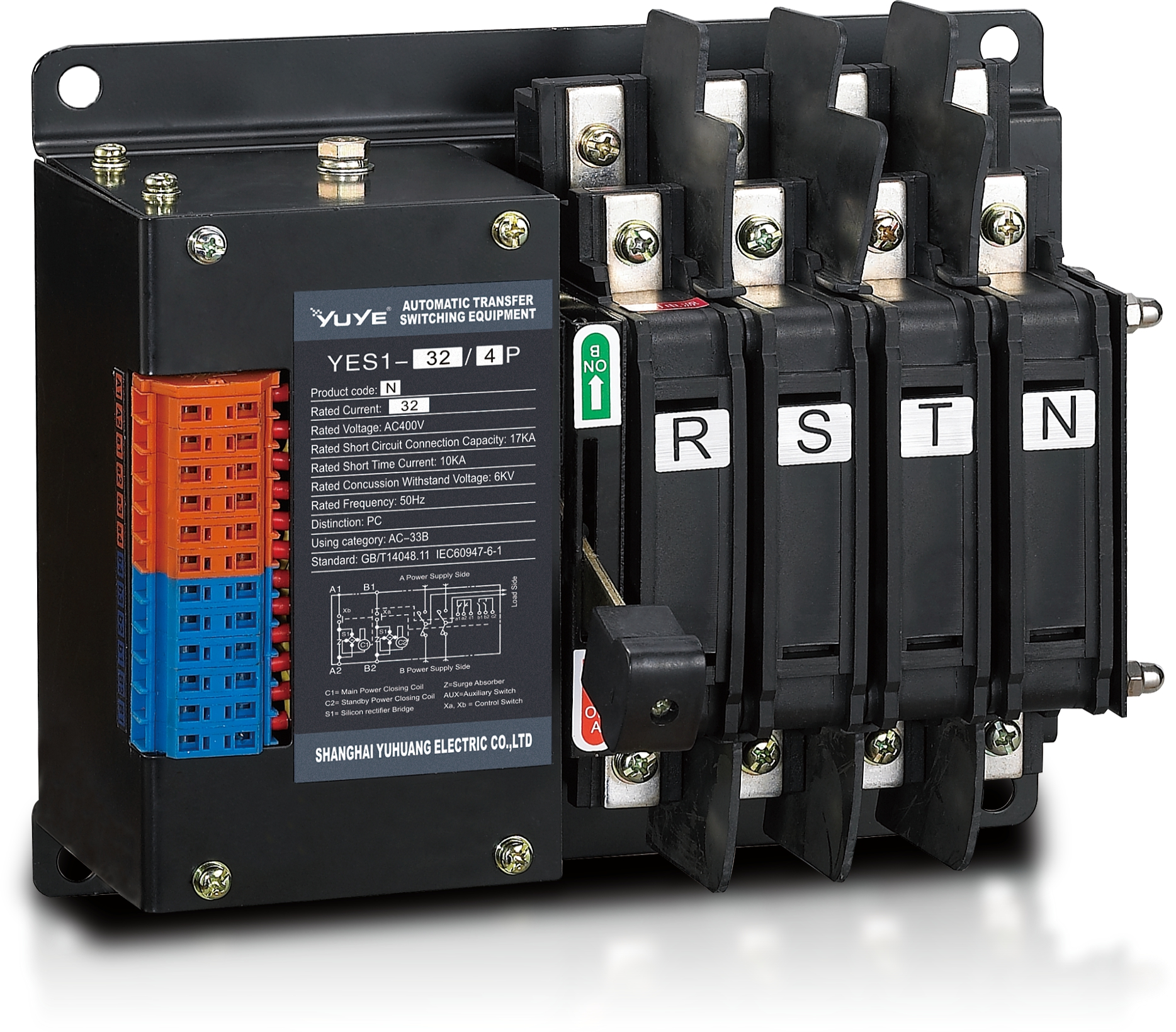 Solenoid-type ATS YES1-32~125N
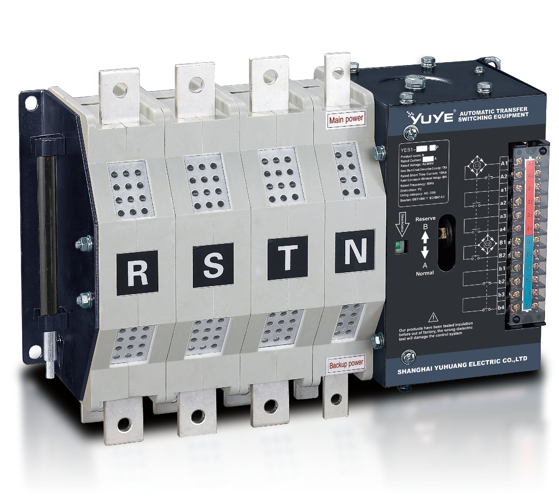 Solenoid-type ATS YES1-250~630N/NT
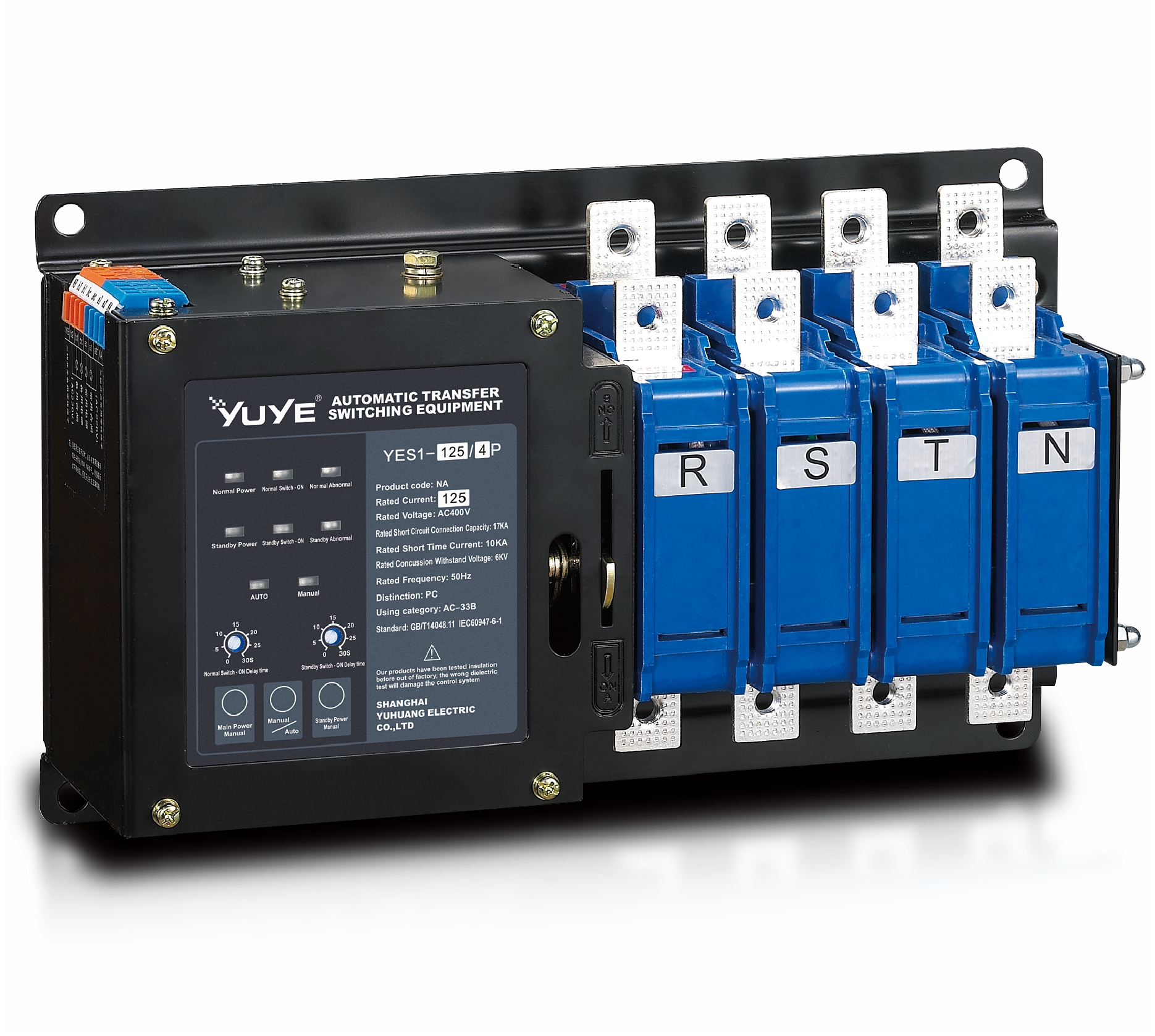 Solenoid-type ATS YES1-32~125NA
 Solenoid-type ATS YES1-63~630SN
 Solenoid-type ATS YES1-1250~4000SN
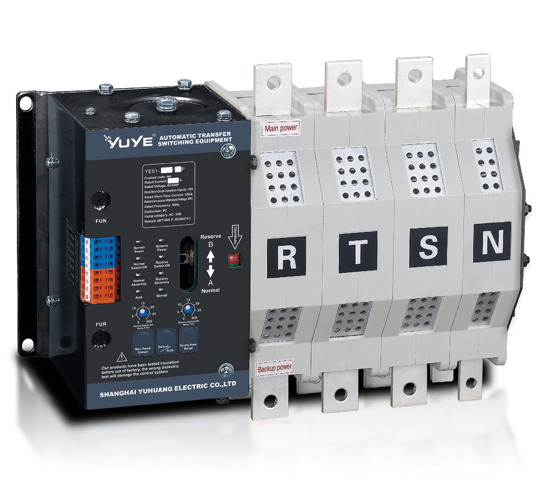 Solenoid-type ATS YES1-250~630NA/NAT
 Solenoid-type ATS YES1-63NJT
 PC ATS YES1-100~1600GN1/GN/GNF
 PC ATS YES1-2000~3200GN/GNF
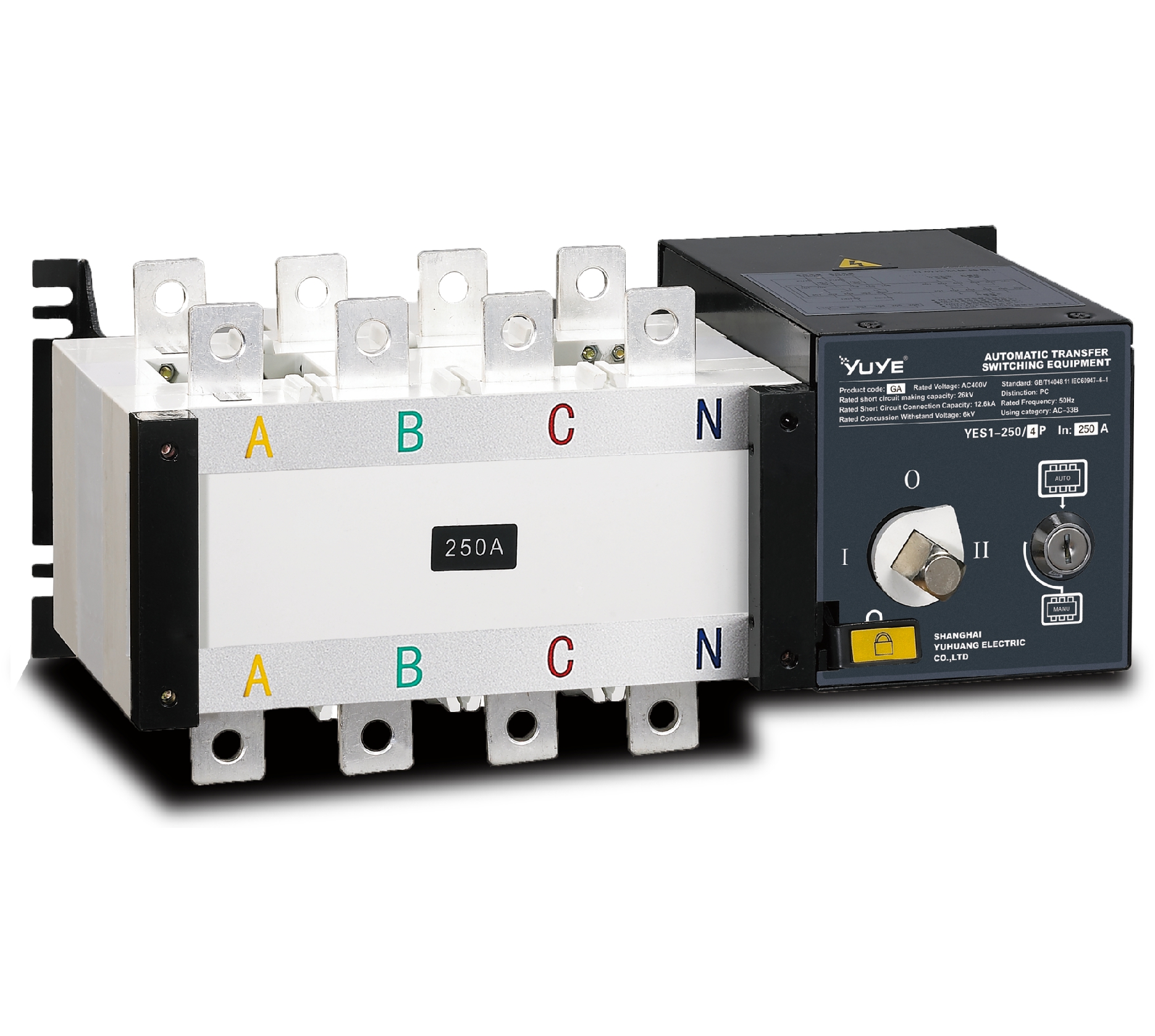 PC ATS YES1-100~3200GA1/GA
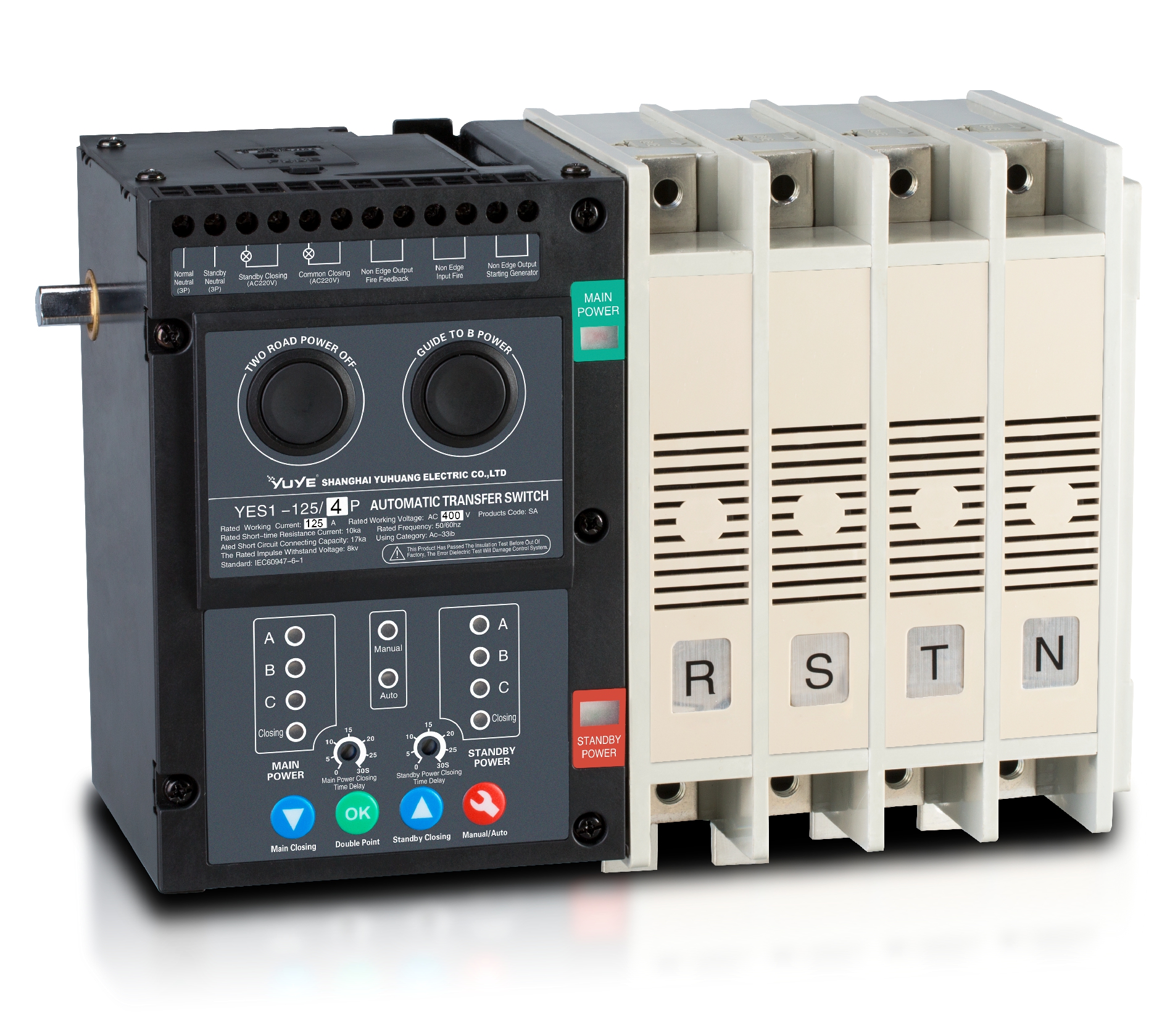 Solenoid-type ATS YES1-63~630SA
 Solenoid-type ATS YES1-63~630L/LA
 Solenoid-type ATS YES1-63~630LA3
 Solenoid-type ATS YES1-63MA
 PC ATS YES1-630~1600M
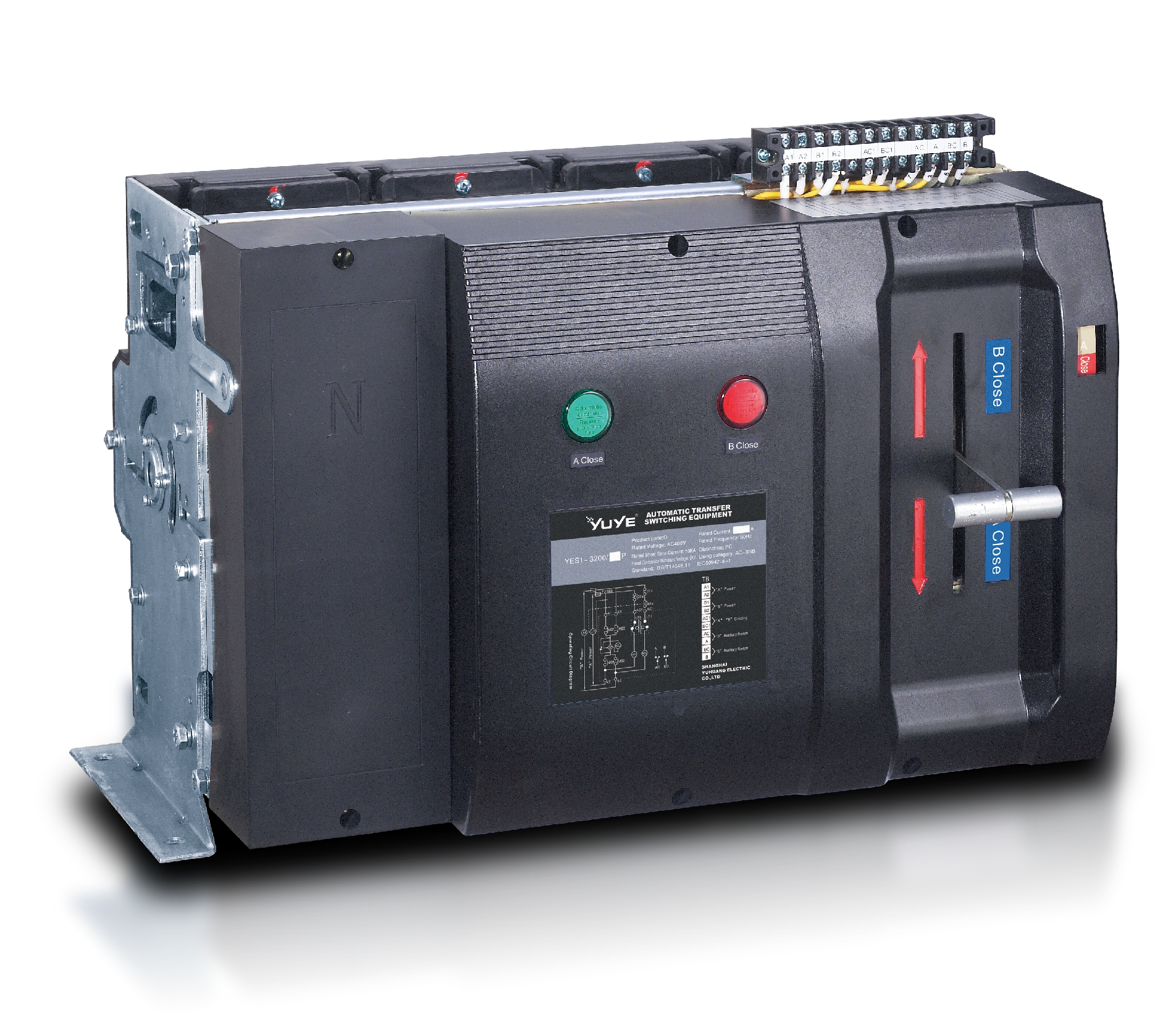 PC ATS YES1-3200Q
 Solenoid-type ATS YES1-4000~6300Q
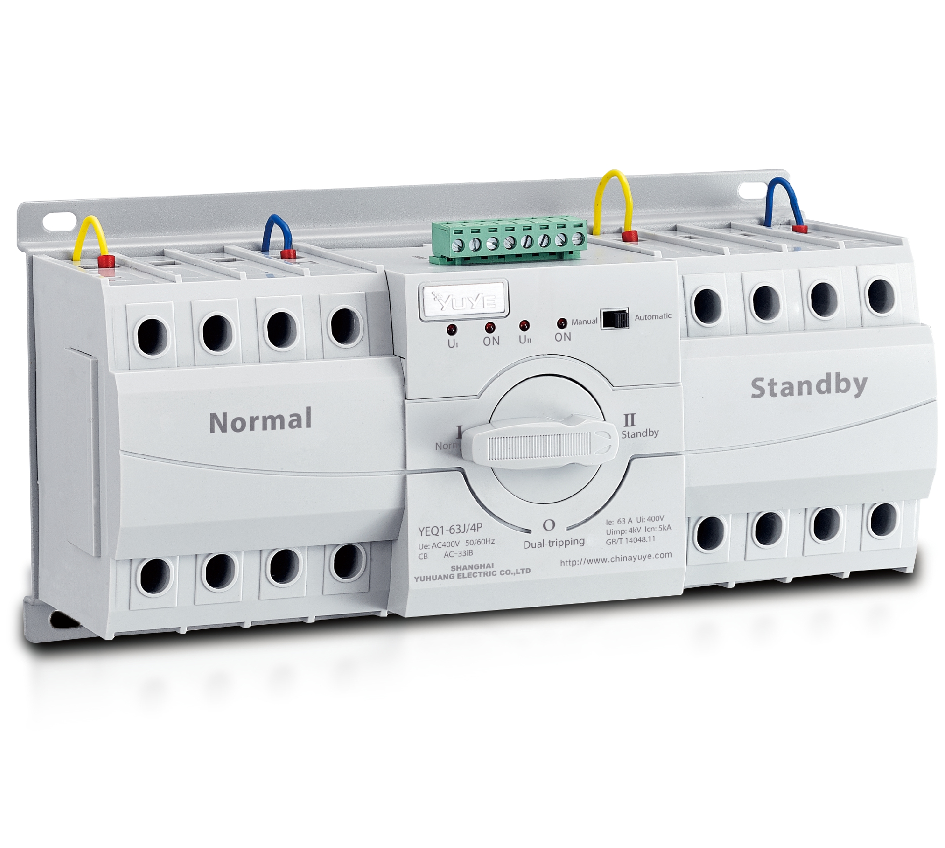 CB ATS YEQ1-63J
 CB ATS YEQ2Y-63
 CB ATS YEQ3-63W1
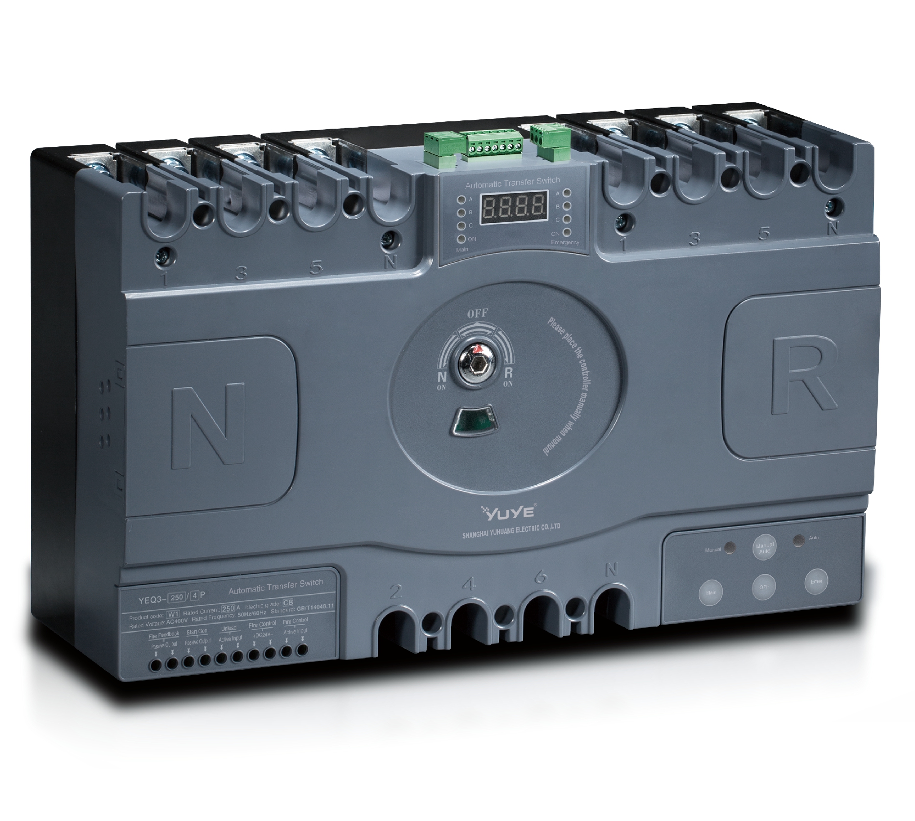 CB ATS YEQ3-125~630W1
 ATS controller Y-700
 ATS Controller Y-700N
 ATS Controller Y-701B
 ATS Controller Y-703N
 ATS Controller Y-800
 ATS Controller W2/W3 Series
 ATS switch Cabinet floor-to-ceiling
 ATS switch cabinet
 JXF-225A power Cbinet
 JXF-800A power Cbinet
 YEM3-125~800 Plastic Shell Type MCCB
 YEM3L-125~630 Leakage Type MCCB
 YEM3Z-125~800 Adjustable Type MCCB
 YEM1-63~1250 Plastic Shell Type MCCB
 YEM1E-100~800 Electronic Type MCCB
 YEM1L-100~630 Leakage Type MCCB
 Air Circuit Breaker YEW1-2000~6300
 Air Circuit Breaker YEW3-1600
 Miniature circuit breaker YEMA2-6~100
 Miniature circuit breaker YEB1-3~63
 Miniature circuit breaker YEB1LE-3~63
 Miniature circuit breaker YEPN-3~32
 Miniature circuit breaker YEPNLE-3~32
 Miniature circuit breaker YENC-63~125
 Load isolation switch YGL-63~3150
 Load Isolation Switch YGL2-63~3150
 DC relay YDC-P20
 DC relay YDC-P250
 DC relay YDC-P400
 DC relay MDC-300M
 DC relay YDC-M400
 DC Isolation Switch YEGL3D-630
 YECPS2-45~125 LCD
 YECPS-45~125 Digital
 CNC Milling/Turning-OEM


