 PC ATS YECT1-2000G
 PC ATS YES2-63~250GN1
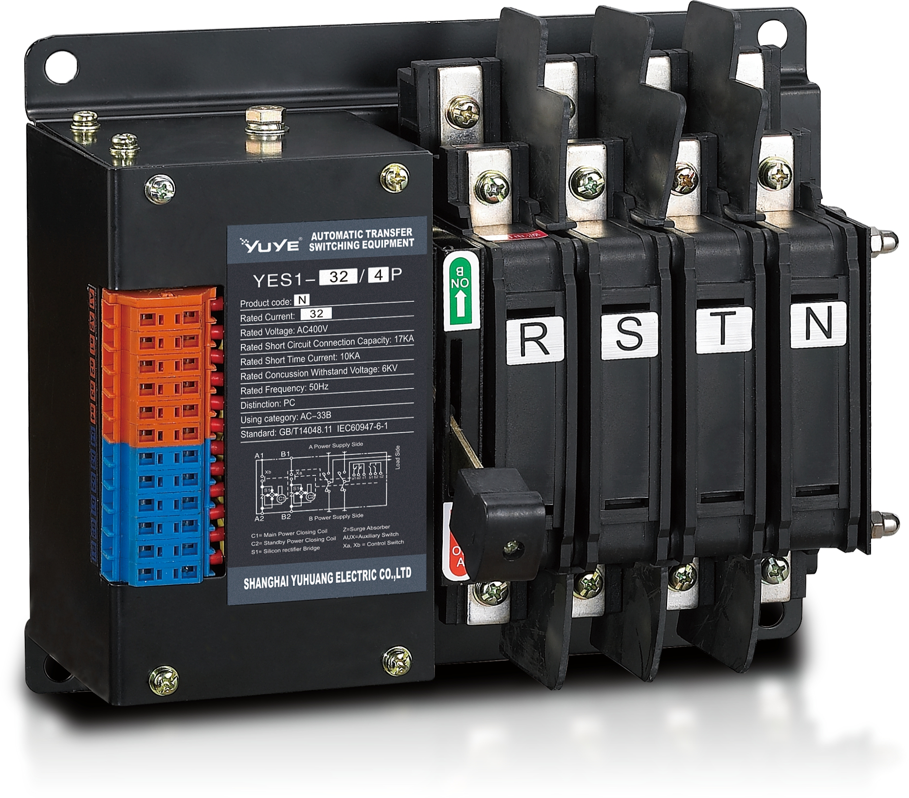 Solenoid-type ATS YES1-32~125N
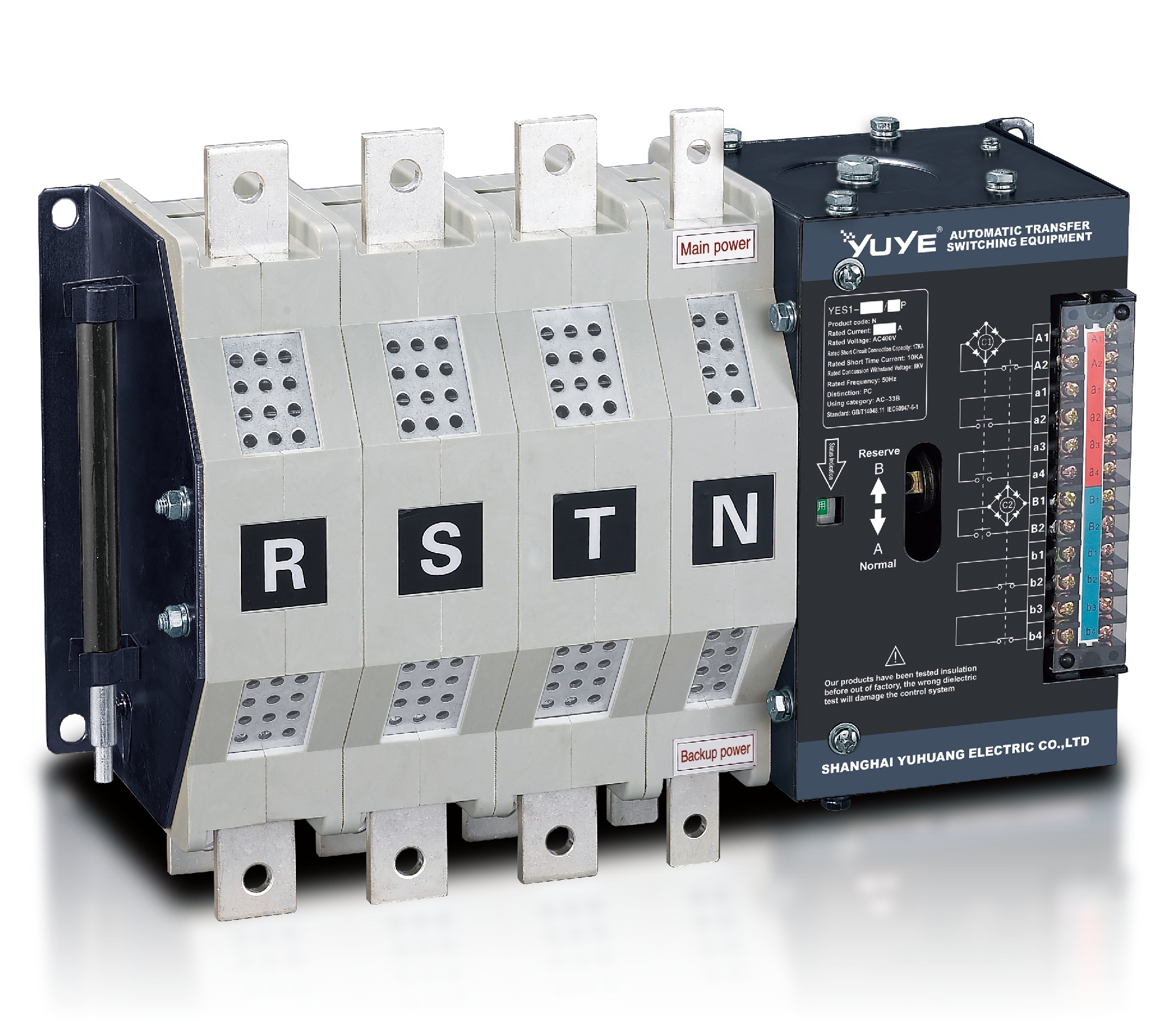 Solenoid-type ATS YES1-250~630N/NT
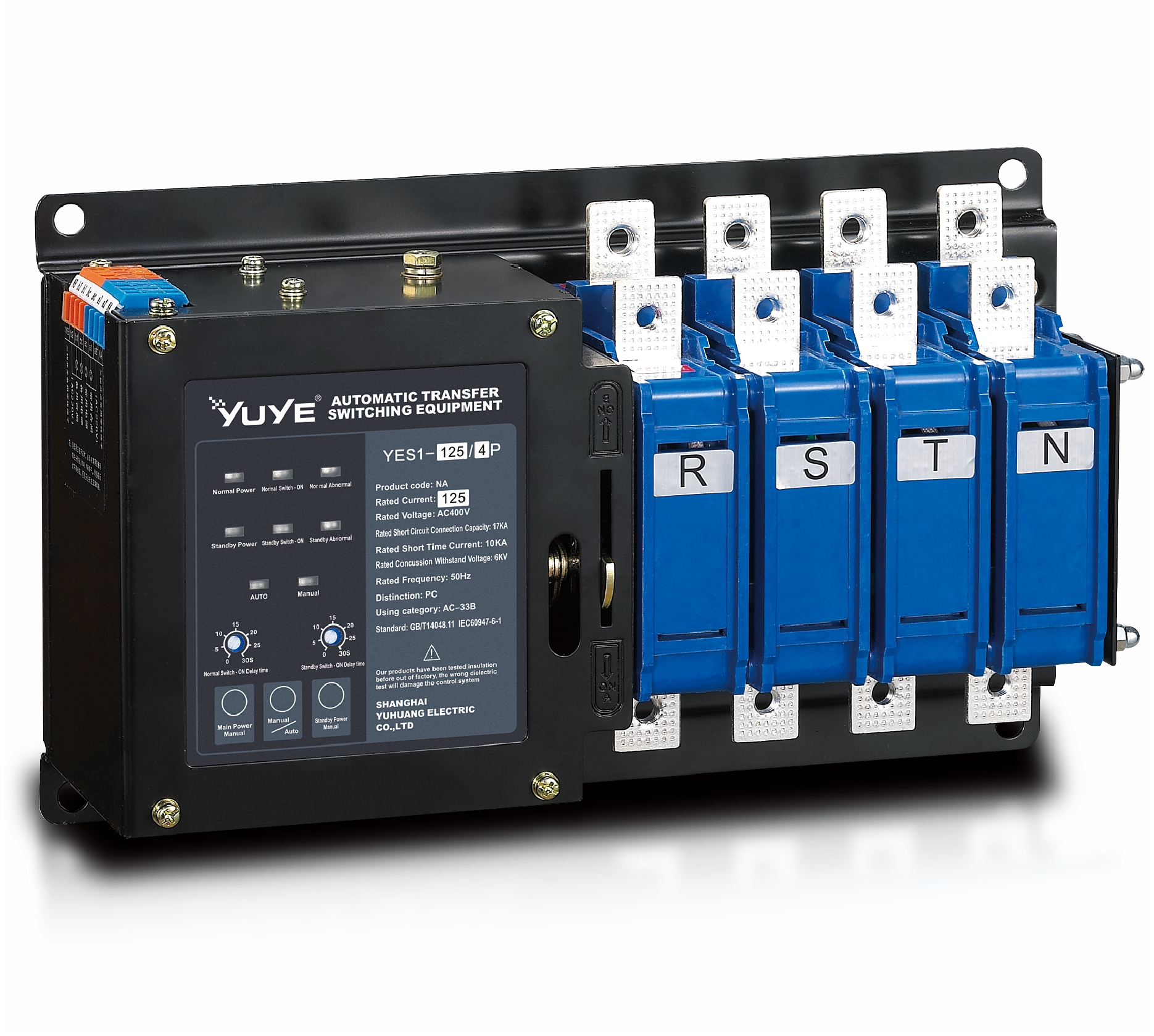 Solenoid-type ATS YES1-32~125NA
 Solenoid-type ATS YES1-63~630SN
 Solenoid-type ATS YES1-1250~4000SN
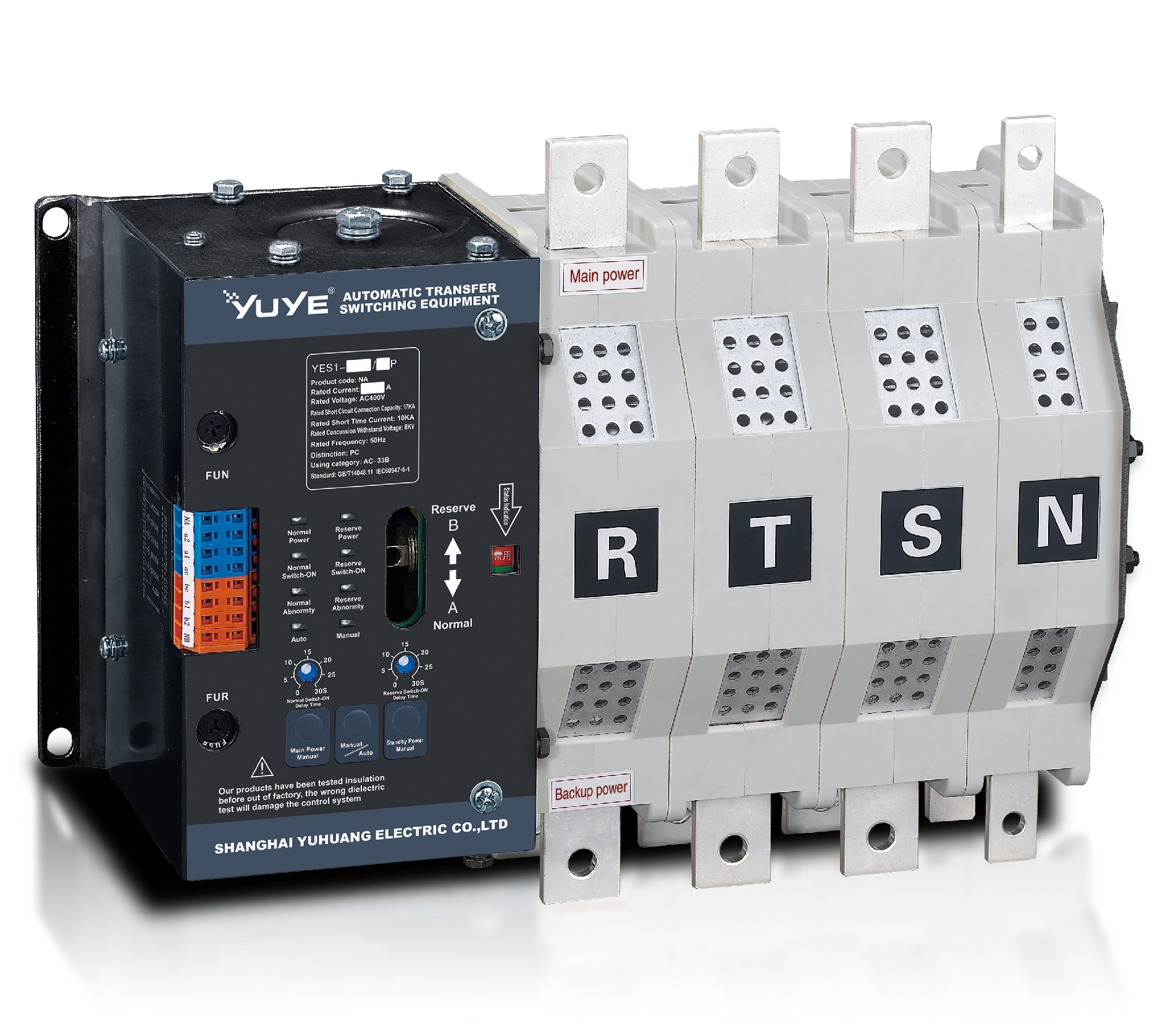 Solenoid-type ATS YES1-250~630NA/NAT
 Solenoid-type ATS YES1-63NJT
 PC ATS YES1-100~1600GN1/GN/GNF
 PC ATS YES1-2000~3200GN/GNF
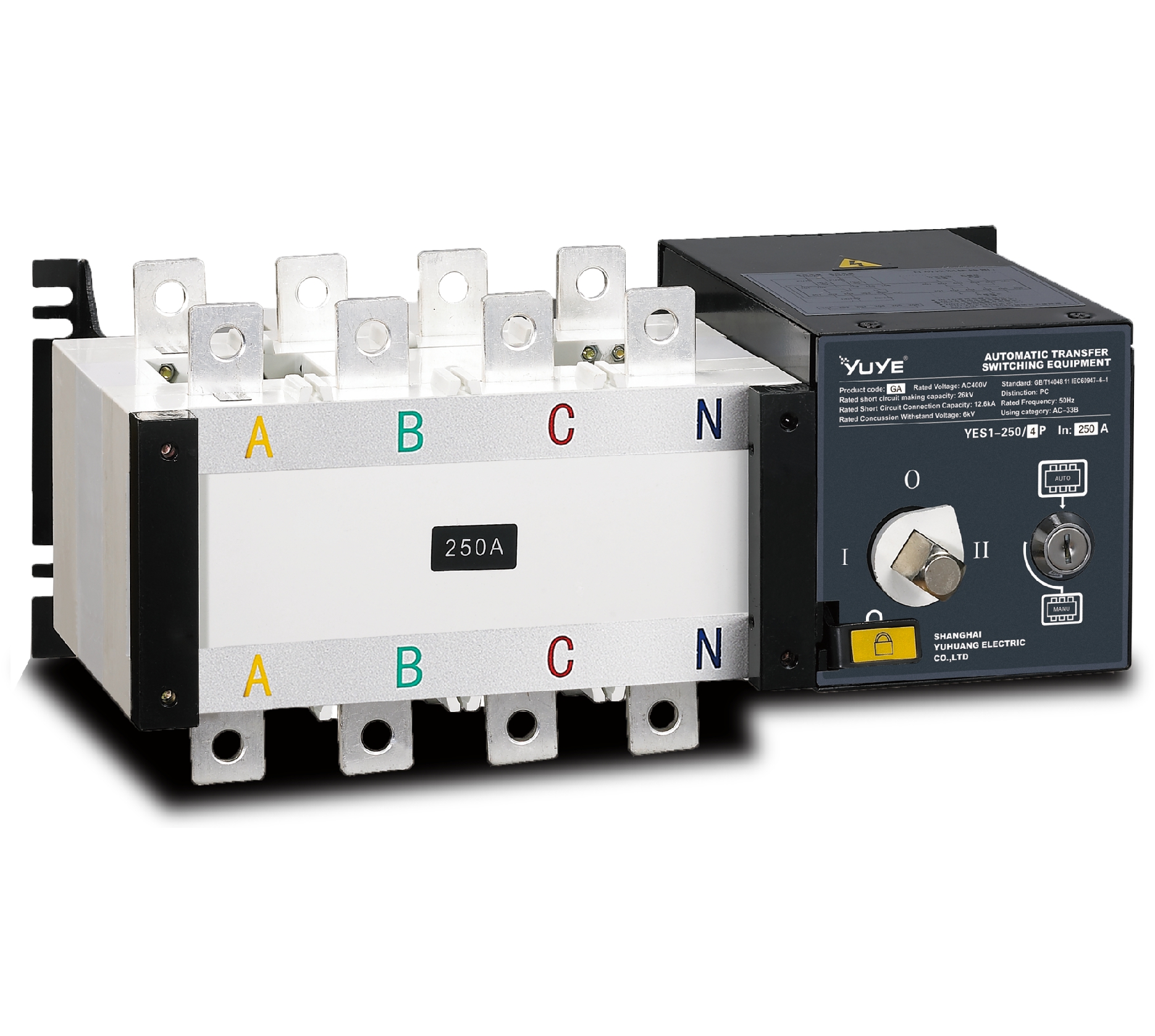 PC ATS YES1-100~3200GA1/GA
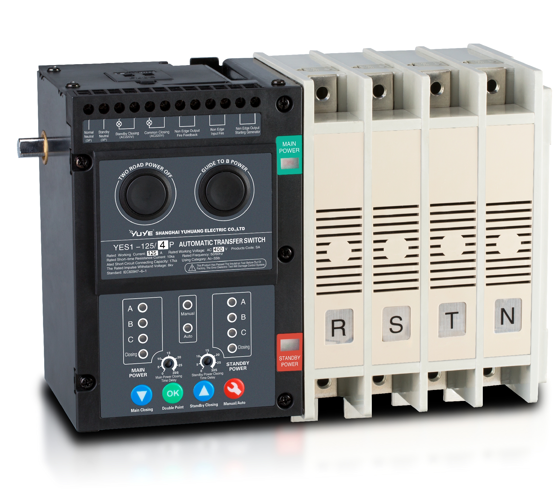 Solenoid-type ATS YES1-63~630SA
 Solenoid-type ATS YES1-63~630L/LA
 Solenoid-type ATS YES1-63~630LA3
 Solenoid-type ATS YES1-63MA
 PC ATS YES1-630~1600M
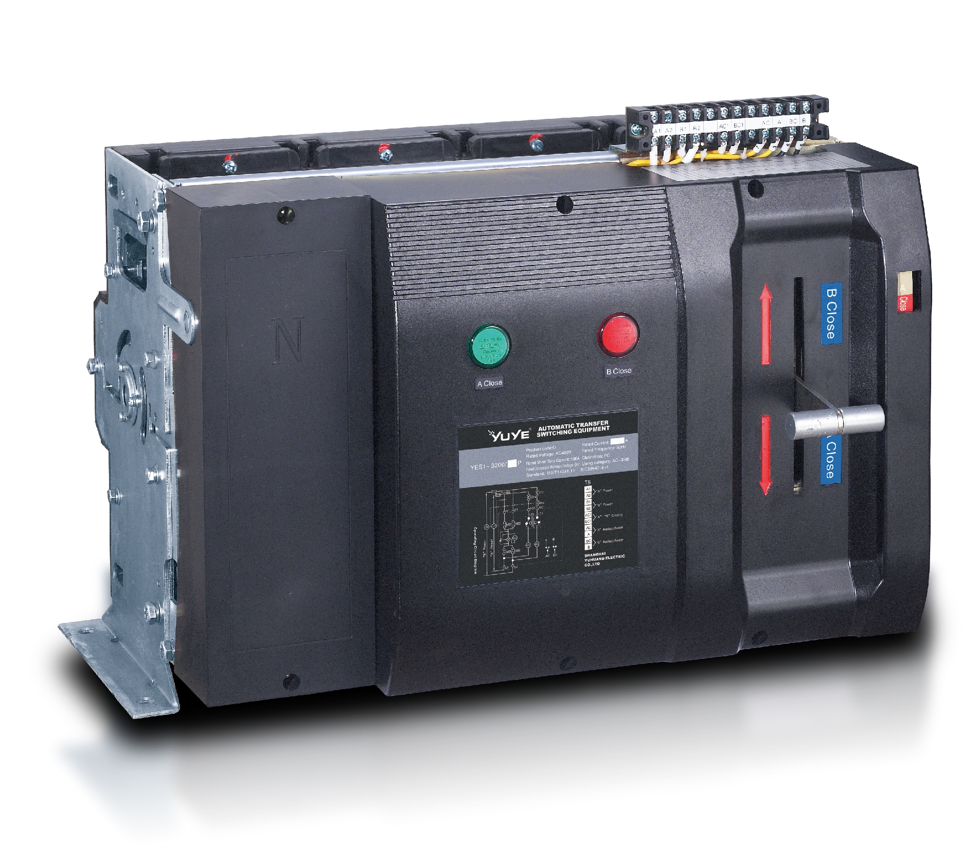 PC ATS YES1-3200Q
 Solenoid-type ATS YES1-4000~6300Q
 CB ATS YEQ1-63J
 CB ATS YEQ2Y-63
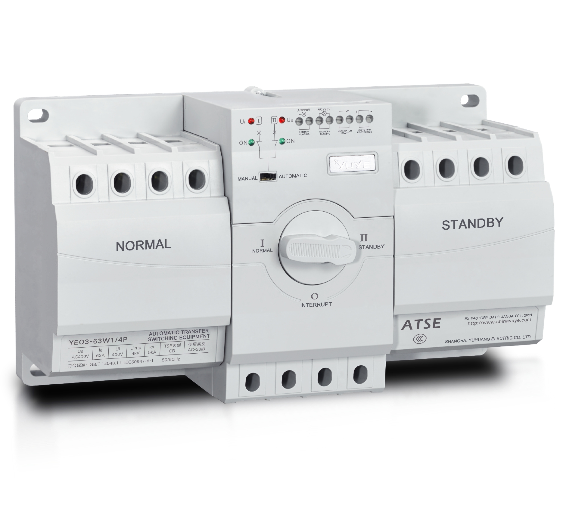 CB ATS YEQ3-63W1
 CB ATS YEQ3-125~630W1
 ATS controller Y-700
 ATS Controller Y-700N
 ATS Controller Y-701B
 ATS Controller Y-703N
 ATS Controller Y-800
 ATS Controller W2/W3 Series
 ATS switch Cabinet floor-to-ceiling
 ATS switch cabinet
 JXF-225A power Cbinet
 JXF-800A power Cbinet
 YEM3-125~800 Plastic Shell Type MCCB
 YEM3L-125~630 Leakage Type MCCB
 YEM3Z-125~800 Adjustable Type MCCB
 YEM1-63~1250 Plastic Shell Type MCCB
 YEM1E-100~800 Electronic Type MCCB
 YEM1L-100~630 Leakage Type MCCB
 Miniature circuit breaker YEMA2-6~100
 Miniature circuit breaker YEB1-3~63
 Miniature circuit breaker YEB1LE-3~63
 Miniature circuit breaker YEPN-3~32
 Miniature circuit breaker YEPNLE-3~32
 Miniature circuit breaker YENC-63~125
 Air Circuit Breaker YEW1-2000~6300
 Air Circuit Breaker YEW3-1600
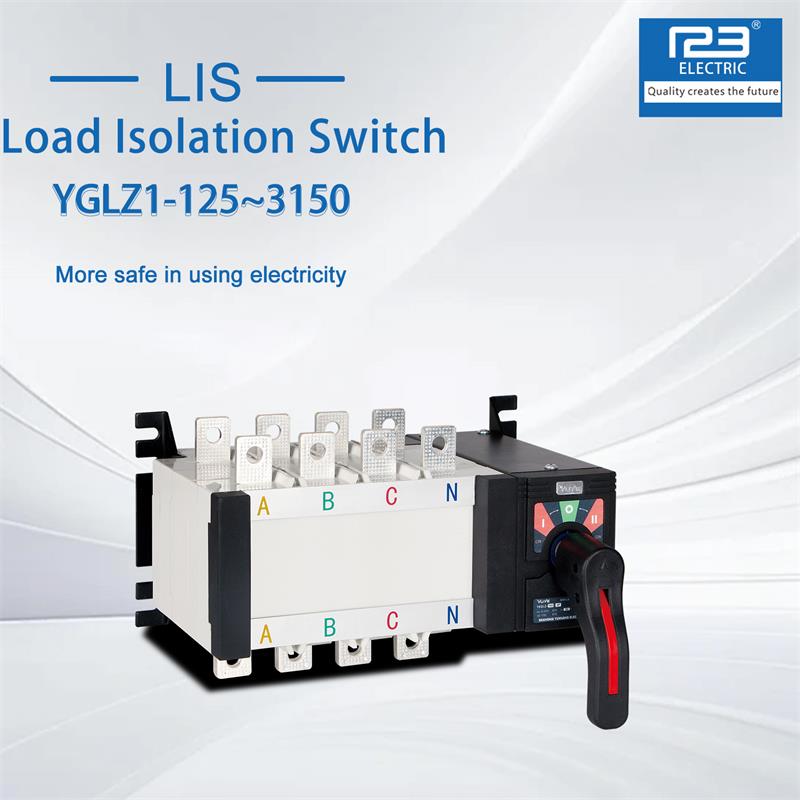
 Load isolation switch YGL-63~3150
 Load Isolation Switch YGL2-63~3150
 YECPS2-45~125 LCD
 YECPS-45~125 Digital
 Manual Changeover Switch YGL-100~630Z1A
 Manual Changeover Switch YGLZ1-100~3150
 CNC Milling/Turning-OEM
 DC relay MDC-300M
 DC Isolation Switch YEGL3D-630
1. Introduction
1.1 Research background and engineering significance of on-site manual switch
Most industrial workshops, power distribution rooms and pumping stations adopt dual automatic-manual control modes. Automatic control systems are vulnerable to signal interference, program crash and power fluctuation, so manual backup operation ensures equipment emergency stop and fault isolation. Standardizing switching control logic can cut safety accidents, reduce maintenance costs and meet industrial electrical safety codes, especially for high-load industrial working conditions.
1.2 Current situation and safety defects of field manual control operation
Most industrial sites adopt empirical manual operation without unified hierarchical standards. Main defects include: inconsistent operator qualifications, single electrical protection without mechanical interlock, lack of abnormal state early warning, and non-updated fragmented operation workflows. These problems lead to frequent avoidable switching operation accidents on site.
1.3 Research purpose, scope and overall technical framework
This research targets conventional low-voltage industrial operation scenes, excluding explosion-proof and high-temperature customized switching devices. It classifies operation risks, establishes hierarchical operation rules, designs dual interlock logic, proposes emergency strategies, and builds updatable operation workflows. The research follows the logic of risk analysis-rule formulation-logic design-emergency optimization-process standardization to realize full-link operation safety control.
2. Risk Identification of On-site Manual Switch Manipulation Scenarios
2.1 Classification of typical application scenarios for on-site manual switches
On-site switching scenarios are divided into three types. Daily debugging scenarios feature low load and low risk for routine maintenance; emergency disposal scenarios feature sudden operation demands and high human error risks for automatic system failure; cross-equipment linkage scenarios involve multi-circuit linkage with the highest safety risk. Different scenarios match exclusive control authority and protection thresholds.
2.2 Human operation risk, equipment failure risk and circuit linkage risk sorting
Three core risks exist in on-site switching operation. Human risks include state misjudgment and violation operation; equipment risks include component aging and insulation damage; circuit risks cover residual current feedback and parallel circuit mutual interference. On-site statistics show human misoperation accounts for 68% of switching accidents, which is the key prevention target.
2.3 Quantitative assessment of safety hidden dangers in manual switching operation
Based on fuzzy risk assessment model, this paper evaluates operation risks from four dimensions and divides risks into four grades. Low-risk tasks allow independent operator operation; medium-risk tasks require on-site guardians; high-risk tasks need dual-person cooperation; extreme-risk tasks require power-off isolation. The assessment results support hierarchical control rule formulation.
3. Hierarchical Safety Control Rules for Field Manual Switch Operation
3.1 Division of operation authority and safety control hierarchy
A four-level operation authority system is established based on risk grades. Level-1 interns handle low-risk debugging; Level-2 on-site electricians conduct medium-risk switching; Level-3 engineers manage high-risk emergency operation; Level-4 management staff approve extreme-risk operation. Identity verification and operation archiving are set to avoid unauthorized cross-level operation.
3.2 Formulation of standard operation constraints for manual switching
Mandatory operation constraints are formulated for on-site switching. Operators must inspect insulation and interlock state before operation; live-line switching is banned in humid open-air sites; protection baffle disassembly is prohibited; 3-5s stay is required to confirm circuit stability; all operation data must be recorded for archiving.
3.3 Matching mechanism between operation procedure and safety control threshold
Unified safety thresholds are set for field switching. Manual switching will be locked when residual current exceeds 30mA, and voice warning triggers when load current exceeds 1.2 times rated value. Operation steps will be suspended automatically once parameters exceed thresholds, and can be resumed only after fault elimination and system reset.
4. Interlock Protection Logic Design of On-site Manual Switch System
4.1 Design principle of electrical and mechanical double interlock structure
This paper designs an electrical-mechanical double interlock structure to avoid single protection failure. PLC-based electrical interlock prevents simultaneous automatic-manual signal input, while mechanical limit structure locks live switching physically. The dual backup structure improves operation safety greatly. The optimized Manual Switch with double interlock reduces misoperation rate by 91% compared with traditional products.
4.2 Optimization of anti-misoperation interlock logic for manual-automatic switching
To solve signal conflict during frequent mode switching, 2s delay interlock logic is optimized: manual terminal keeps locked under stable automatic operation, and unlocks only when automatic system sends fault signal. One-way mode switching is adopted to allow only automatic-to-manual switching, preventing circuit impact and program disorder.
4.3 Hardware and software implementation scheme of protection interlock module
The interlock module adopts anti-interference hardware with independent power supply for electromagnetic industrial environments. Its ladder diagram-based software runs independently without host program interference, supporting on-site and remote dual reset modes to facilitate fault handling and daily debugging.
5. Abnormal State Judgment and Emergency Control Strategy for Manual Switch
5.1 Definition and feature extraction of common abnormal working states
Four typical abnormal states are defined: contact adhesion, shell leakage, signal lag and mechanical jamming. Real-time temperature, current and vibration data are collected to extract abnormal feature thresholds, building a feature database for rapid abnormal identification.
5.2 Real-time abnormal state judgment algorithm and identification model
A lightweight threshold algorithm is applied for local edge computing, finishing abnormal judgment within 0.5s. Multi-parameter joint judgment avoids false alarms, and the algorithm adapts to unstable circuit signal conditions of old industrial sites to improve identification accuracy.
5.3 Emergency cut-off, reset and fault isolation control strategies
Hierarchical emergency strategies match different faults. Slight signal lag triggers warning and operation lock; medium leakage or jamming leads to branch circuit power-off; severe contact adhesion requires full-site power-off and professional component replacement. This strategy balances operational safety and production efficiency.
6. Standardized Iteration of Manual Switch Safe Control Workflow
6.1 Establishment of full-life cycle safe operation workflow
A full-life cycle workflow covering component inspection, installation, operation, maintenance and scrapping is established. Standard steps including identity verification, state confirmation and data recording are enforced, and quarterly component detection is arranged to realize traceable whole-process safety management.
6.2 Optimization and iteration path of field control process
The control workflow updates dynamically every six months. Risk indicators, safety thresholds and operation steps will be revised timely according to new faults, circuit upgrading and hardware iteration, to match updated on-site production conditions.
6.3 Engineering application standard and popularization specification
Combined with national low-voltage electrical codes, this research forms universal switching operation specifications for factories, pumping stations and power distribution rooms. Pilot application proves the workflow eliminates switching safety accidents within one year. As the core control carrier, the upgraded Manual Switch realizes full safety linkage with on-site control systems.
7. Conclusion and Prospect
7.1 Summary of core safe control logic research results
This paper completes systematic research on on-site manual switch safety control. It realizes risk grading assessment, builds hierarchical authority rules, designs dual anti-misoperation interlock logic, proposes hierarchical emergency strategies, and establishes iterable operation workflows. The research solves disordered operation and insufficient protection problems of traditional manual switching systems.
7.2 Deficiencies of current control system
This study has two limitations: it only applies to conventional low-voltage switches, excluding special anti-corrosion and explosion-proof models; the lightweight algorithm lacks big-data-based fault prediction function, which needs further optimization in follow-up research.
7.3 Future intelligent upgrading direction of on-site manual switch
Future research focuses on intelligent upgrading: adding IoT sensing modules for remote monitoring, adopting machine learning for fault prediction, building digital twin risk simulation models, and developing adaptive interlock logic for special-condition switches to realize universal field switching safety control.
References
- García J, Martínez R. Mechanical-Electrical Interlock Design for Industrial Manual Control Switches[J]. IEEE Transactions on Industry Applications, 2022, 58(4): 4126-4134.
- Hoffmann T, Weber S. On-site Operation Risk Assessment and Anti-misoperation Control of Low-voltage Switch Components[J]. Electrical Engineering, 2023, 105(2): 891-900.
- International Electrotechnical Commission. IEC 60947-1: Low-voltage switchgear and controlgear – General rules[S]. Geneva: IEC, 2021.
- Park S, Kim H. Safety Threshold Setting and Emergency Logic Optimization for Field Manual Switching System[J]. Journal of Electrical Engineering & Technology, 2024, 19(1): 567-575.
- Schulz M. Lifecycle Safety Management and Standardized Operation of Industrial Manual Switch Devices[J]. Process Safety Progress, 2023, 42(3): e12987.
FAQ
Q1: What is the core application premise of this set of manual switch safe control logic?
A1: It applies to conventional 220V/380V low-voltage industrial indoor and semi-outdoor control scenes, excluding high-voltage, explosion-proof, corrosive and extreme-temperature working conditions.
Q2: Can the double interlock structure be modified on existing old switching equipment?
A2: Yes. The split interlock parts can be installed externally, requiring no main circuit modification for old equipment upgrading.
Q3: How often does the manual switch safety control workflow need to be iterated?
A3: It iterates every six months by default, and updates in advance if circuit load or on-site faults change.
Q4: What should operators do if the interlock system automatically locks the switching operation?
A4: Forbid forced disassembly. Check circuit faults, remove hidden dangers, and apply administrator reset for unlocking.
Q5: Does this control logic increase the difficulty of daily on-site operation?
A5: No. System background completes automatic verification and warning, which simplifies and standardizes manual operation.