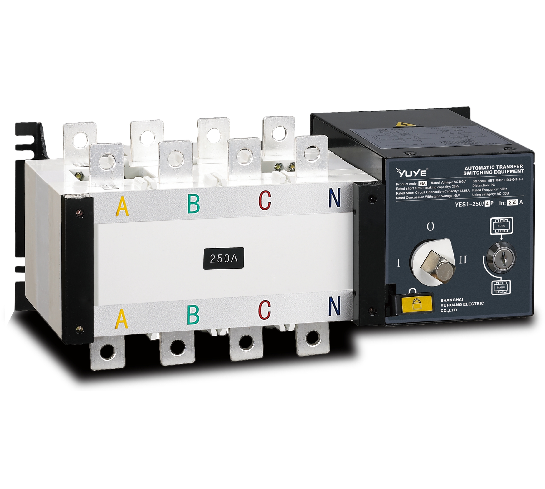
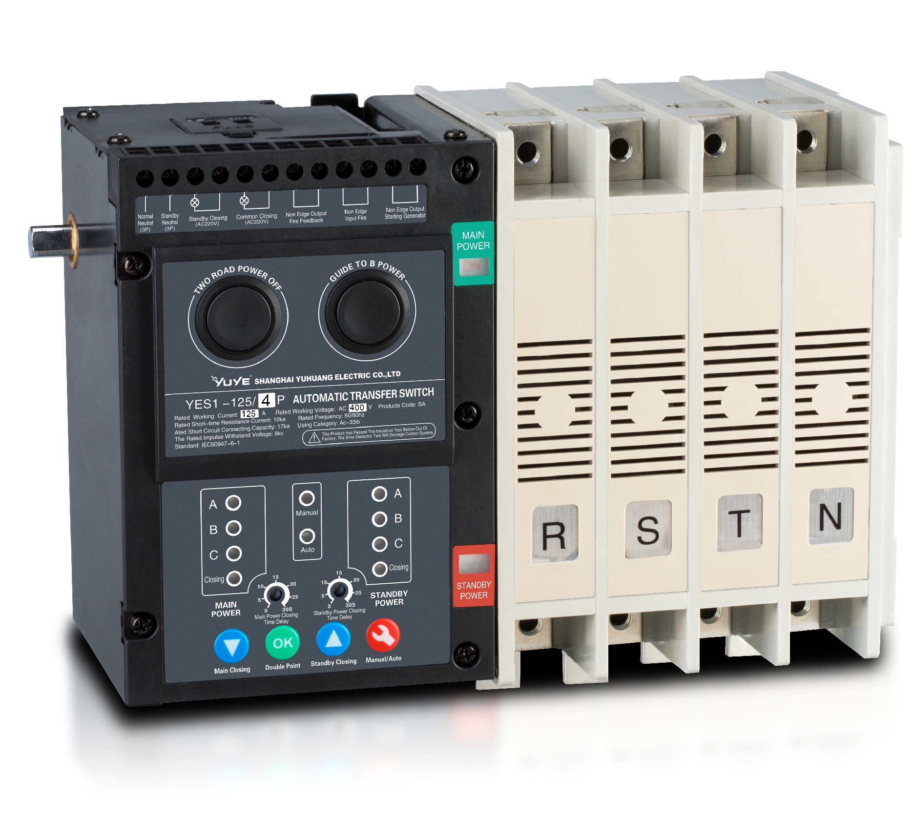
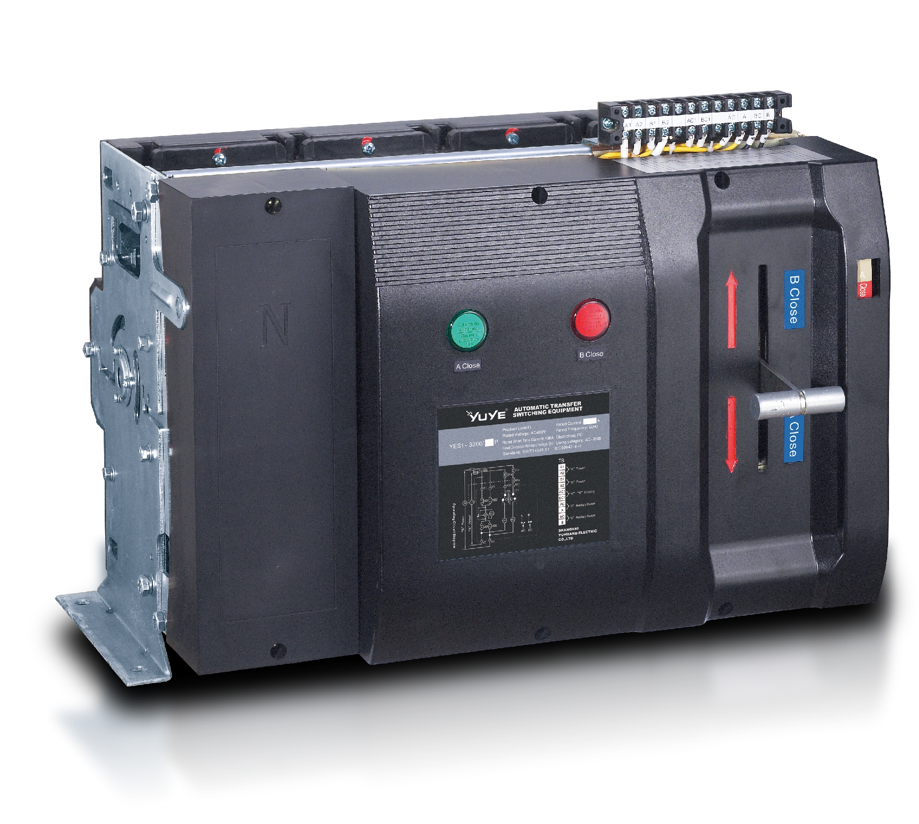
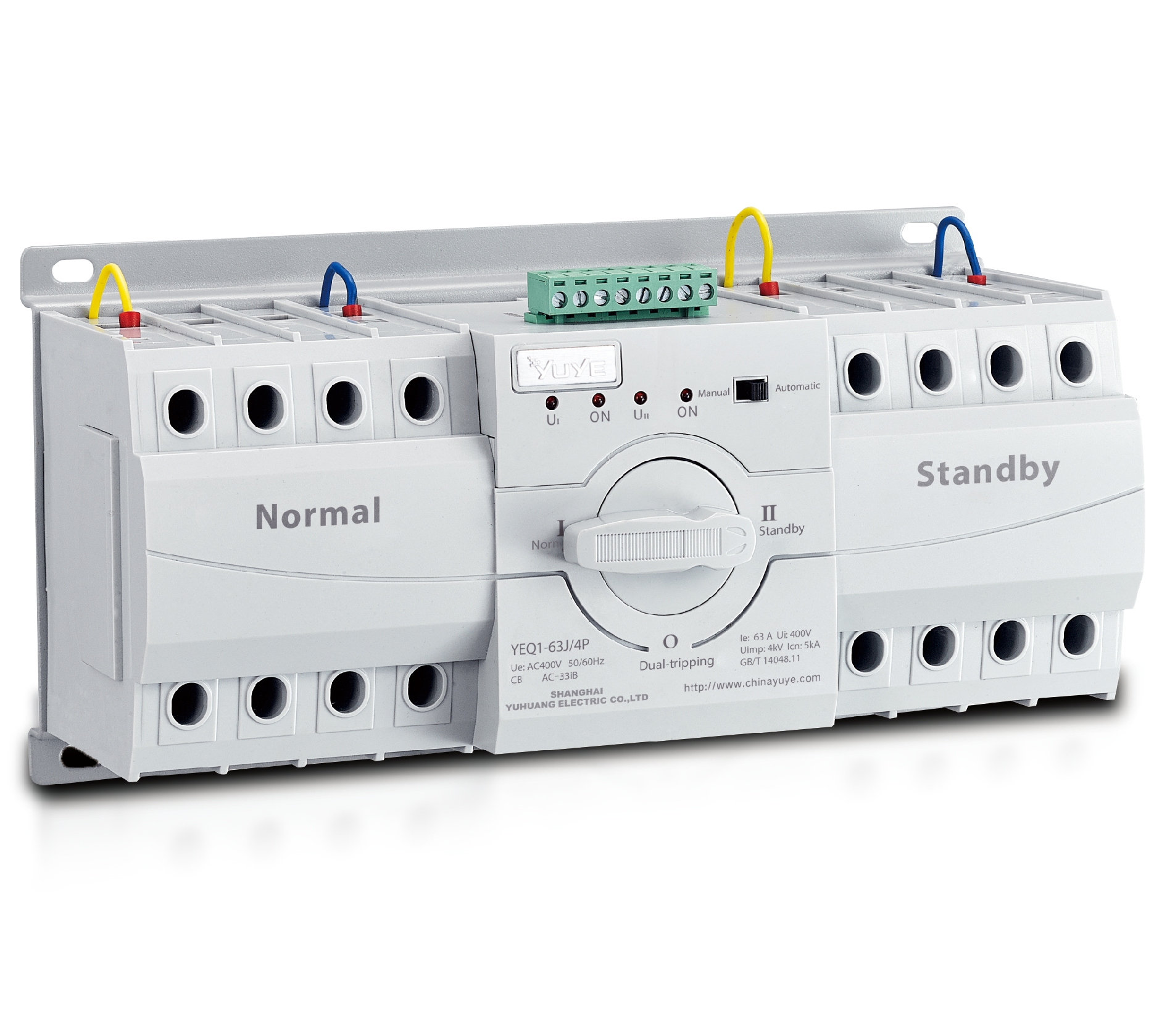
PC ATS YECT1-2000G
PC ATS YES2-63~250GN1
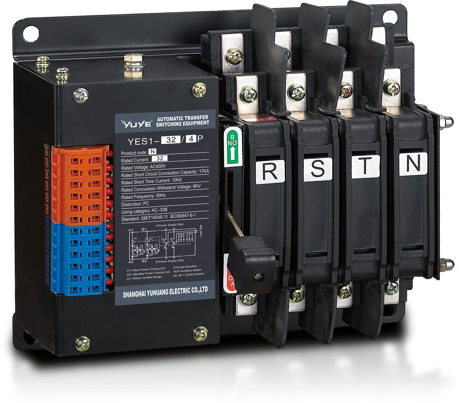
Solenoid-type ATS YES1-32~125N
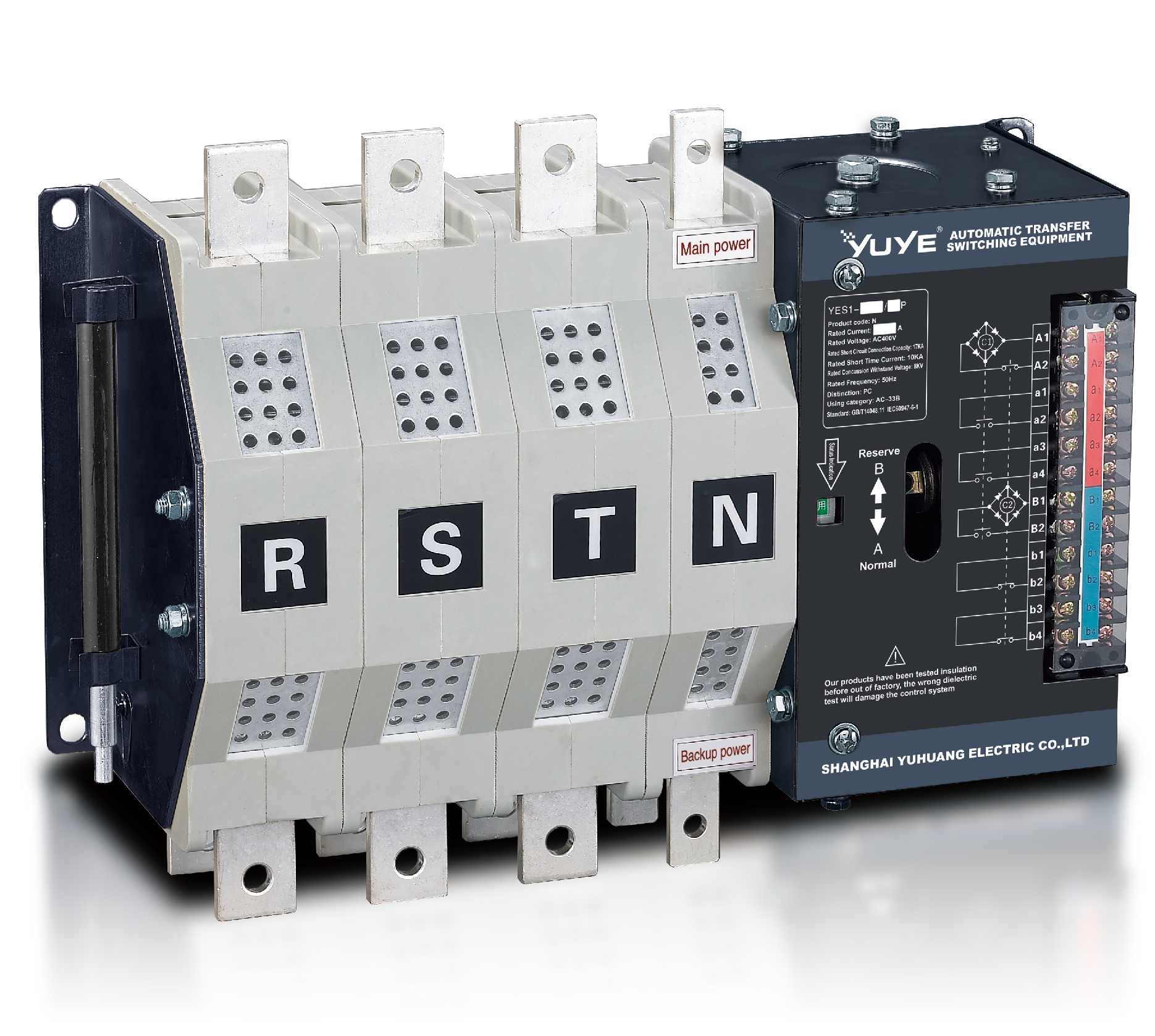
Solenoid-type ATS YES1-250~630N/NT
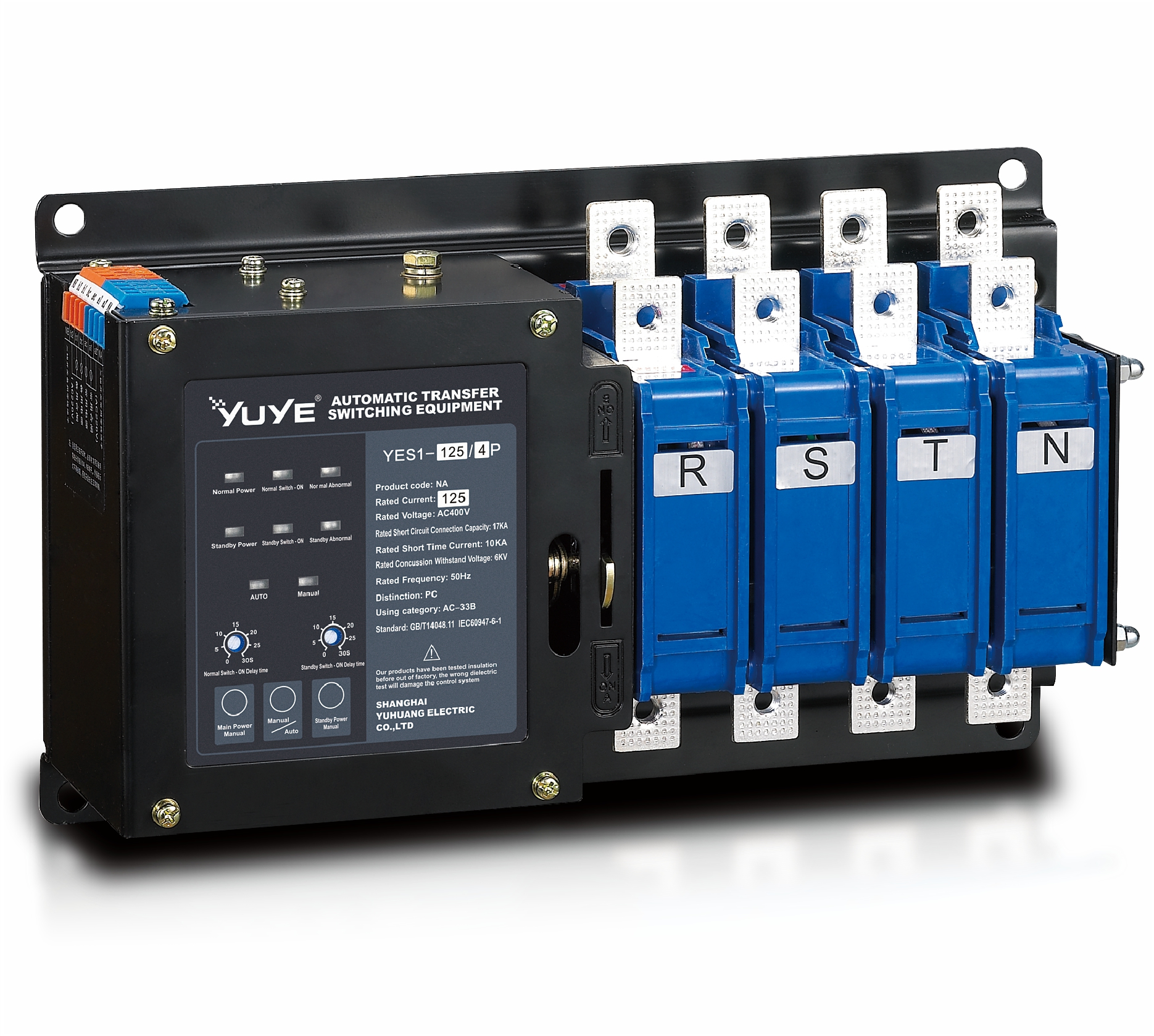
Solenoid-type ATS YES1-32~125NA
Solenoid-type ATS YES1-63~630SN
Solenoid-type ATS YES1-1250~4000SN
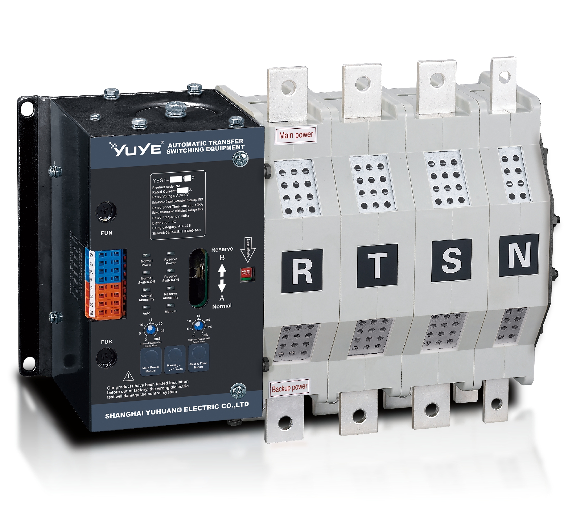
Solenoid-type ATS YES1-250~630NA/NAT
Solenoid-type ATS YES1-63NJT
PC ATS YES1-100~1600GN1/GN/GNF
PC ATS YES1-2000~3200GN/GNF
PC ATS YES1-100~3200GA1/GA
Solenoid-type ATS YES1-63~630SA
Solenoid-type ATS YES1-63~630L/LA
Solenoid-type ATS YES1-63~630LA3
Solenoid-type ATS YES1-63MA
PC ATS YES1-630~1600M
PC ATS YES1-3200Q
Solenoid-type ATS YES1-4000~6300Q
CB ATS YEQ1-63J
CB ATS YEQ2Y-63
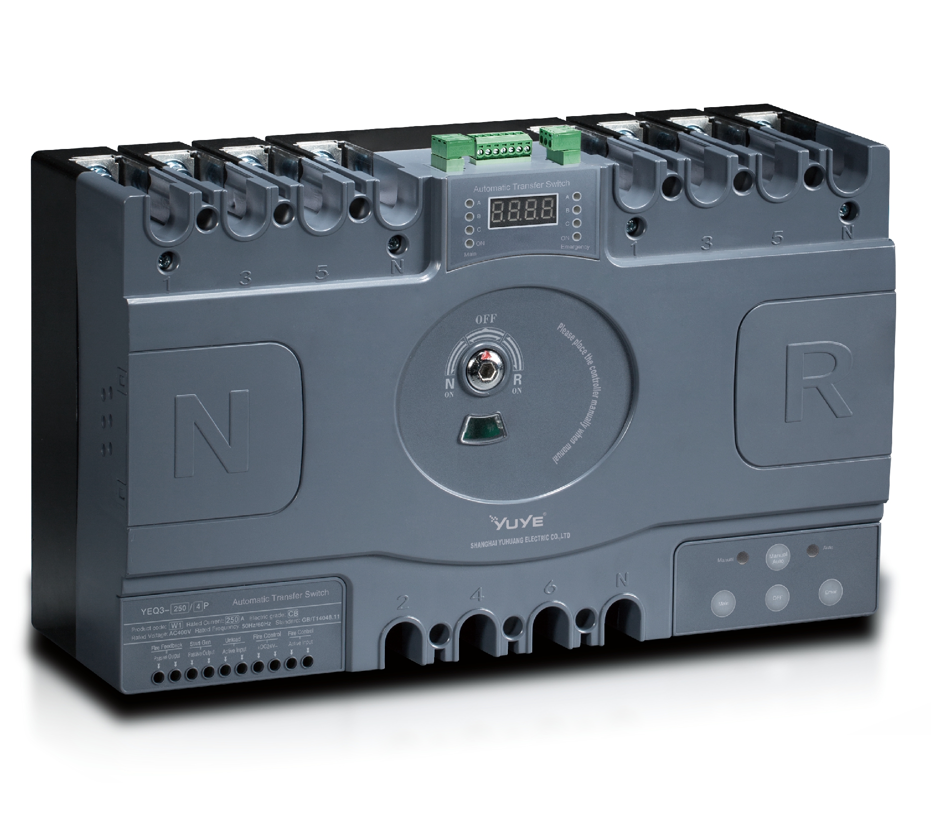
CB ATS YEQ3-63W1
CB ATS YEQ3-125~630W1
ATS controller Y-700
ATS Controller Y-700N
ATS Controller Y-701B
ATS Controller Y-703N
ATS Controller Y-800
ATS Controller W2/W3 Series
ATS switch Cabinet floor-to-ceiling
ATS switch cabinet
JXF-225A power Cbinet
JXF-800A power CbinetSo, what does an Ac Automatic Transfer Switch actually do? In short, it keeps essential power moving when the normal supply drops out. It watches voltage, spots an outage, then moves the load over to a standby generator or another secondary source. And it does this automatically—often fast enough that people inside barely notice the lights blink. That's a big deal in hospitals, data centers, factories, retail stores, and homes with critical equipment.
“An automatic transfer switch is only as dependable as the system around it,” says Mark A. Carlson, a power-systems engineer with Eaton. That point is worth sitting with. Even a reliable Ac Automatic Transfer Switch depends on correct sizing, suitable protection, proper wiring, and regular testing. It can’t fix a weak generator, an overloaded circuit, or a neglected battery. That’s the uncomfortable truth.
A well-chosen switch can cut downtime, protect sensitive equipment, and give operators more confidence. It also means someone doesn’t have to stand next to energized equipment during an outage. Small details really matter here. A loose terminal can heat up. A delayed transfer can halt production. A wrong neutral configuration can lead to serious performance issues.
This guide walks through why organizations use an Ac Automatic Transfer Switch, how the transfer sequence works, and where its limits show up. We’ll look at practical installation concerns, maintenance routines, and differences between applications. The device is useful—but it’s not magic. Good engineering still matters.
An AC automatic transfer switch is an electrical device that moves a load between two alternating-current power sources. Usually, one source is normal utility power, while the other comes from a generator or backup supply. The switch monitors voltage and frequency through control circuits. If the primary source fails, it disconnects that source before connecting the backup. This prevents both sources from feeding the same circuit at once. It is not a generator. It only manages the transfer.
Inside the enclosure, contactors or motor-driven switching mechanisms handle the power path. A control panel may add adjustable delays, manual operation, alarms, and source-status indicators. These features help protect pumps, communication equipment, medical systems, and other critical loads. Transfer timing matters. A delay can prevent switching during a brief voltage dip, but an excessive delay may interrupt sensitive equipment. Real installations are not always perfect; unclear labels, poor maintenance, or incorrect capacity calculations can create avoidable risks. A qualified electrician should verify ratings, grounding, enclosure conditions, and local requirements before commissioning.
Tips: Match the switch rating to the connected load, not merely the generator size. Test the transfer under controlled conditions and record the results. Inspect terminals for heat marks, loose connections, or dust. Keep the operating instructions near the equipment. Small details matter.
Why Use an AC Automatic Transfer Switch?
How an AC Automatic Transfer Switch Operates
An AC automatic transfer switch monitors two power sources continuously. One source is usually the utility supply, while the other may be a generator or backup feeder. Voltage, frequency, and phase conditions are checked through sensing circuits. When the primary source fails, the controller confirms the fault before acting. This short delay helps prevent transfers caused by brief voltage dips.
After verification, the controller sends a signal to the backup source. The generator may need several seconds to start and stabilize. Once acceptable power is detected, an electrically operated mechanism moves the load from the primary source. Mechanical and electrical interlocks prevent both sources from connecting at the same time. That detail is critical. A failed interlock could create dangerous equipment damage or an unstable supply path.
When utility power returns, the switch usually waits through an adjustable retransfer delay. Stable power matters more than speed. The load then moves back, and the generator runs briefly for cooling before stopping. In field inspections, loose terminals, poor ventilation, and neglected testing cause many avoidable problems. A switch can look clean and still respond slowly. Testing should simulate source failure under controlled conditions, not merely press a local button. Settings also need review after major load changes. The process is reliable, but not automatic in every sense; people must maintain, test, and question it.
Typical AC automatic transfer switch operating sequence during a utility power failure and recovery
An AC automatic transfer switch continuously monitors the utility supply. When the voltage becomes unacceptable, it starts the standby generator, waits for stable voltage and frequency, and transfers the load to the alternate source. After utility power returns and remains stable, the switch retransfers the load and allows the generator to cool down before stopping. Actual delay settings depend on the installation and controller configuration.
An AC automatic transfer switch keeps critical loads powered when the primary source fails. It monitors voltage and frequency continuously. When abnormal conditions appear, it disconnects the failed source and connects a standby source, often within seconds. This process protects servers, medical equipment, pumps, and production controls from avoidable interruption.
Fast switching matters. Uptime Institute’s 2024 Annual Outage Analysis reported that 54% of surveyed outages caused losses above $100,000. An automatic switch cannot prevent every failure. It can, however, shorten the electrical gap and reduce manual response time. A technician may need several minutes to reach a panel. The switch reacts immediately. That difference can protect temperature-sensitive rooms, restart-sensitive machinery, and essential lighting.
Reliability depends on correct settings and testing. The controller should verify source voltage, phase sequence, and frequency before transfer. Adjustable time delays can prevent unnecessary switching during brief voltage dips. Too much delay is also a problem. It may leave equipment unpowered longer than expected. IEC 60947-6-1 provides a recognized framework for transfer switching equipment, but site conditions still matter. Commissioning should include simulated source loss, return-to-normal testing, and inspection of cable terminations. No switch is perfect. Poor maintenance can quietly defeat a well-designed system.
Why Use an AC Automatic Transfer Switch?
AC automatic transfer switches support reliable power distribution when a primary source fails. In data centers, hospitals, factories, and commercial buildings, they transfer critical loads to generators or alternate feeders. The Uptime Institute’s 2024 Annual Outage Analysis reports that power problems caused about 54% of recorded data center outages. That figure makes source switching a practical risk-control measure, not merely an electrical upgrade.
Data centers increasingly need stable power. The International Energy Agency’s Electricity 2024 report estimates that global data center electricity use could exceed 1,000 TWh by 2026. An AC ATS helps protect servers, cooling equipment, pumps, and communication systems during voltage loss or source maintenance. In hospitals, it can support operating rooms and life-safety systems. In factories, it reduces process interruptions and protects control equipment from abrupt shutdowns.
Field commissioning also shows a less comfortable truth. An ATS is not a magic shield. Incorrect phase settings, weak generator capacity, or poor maintenance can still cause failure. Engineers should check transfer time, short-circuit ratings, neutral switching, bypass arrangements, and load priorities. IEC 60947-6-1 provides a useful reference for transfer switching equipment, while emergency power installations should align with applicable local safety codes. The best design is tested under realistic load conditions, not only during a quiet inspection.
| Application | Typical Power Sources | Common Voltage Range | Typical Current Range | Transfer Mode | Primary Benefit |
|---|---|---|---|---|---|
| Residential Buildings | Utility supply and standby generator | 120/240 V or 230/400 V | 40–400 A | Open transition | Automatically supplies essential household loads during utility outages. |
| Commercial Offices | Utility feeder and emergency generator | 208/120 V or 400/230 V | 100–1,600 A | Open or delayed transition | Maintains power for lighting, elevators, security, and critical building systems. |
| Data Centers | Independent utility feeders, generators, or UPS outputs | 208/120 V, 400/230 V, or medium-voltage systems | 200–4,000 A per transfer path | Open, delayed, or closed transition | Improves source availability for servers, cooling, and network equipment. |
| Healthcare Facilities | Normal utility source and emergency generator system | 120/208 V, 277/480 V, or 400/230 V | 100–3,000 A | Open or delayed transition | Supports continuity for life-safety, critical care, and essential electrical systems. |
| Industrial Plants | Utility service and generator, alternate feeder, or on-site generation | 400/230 V, 480/277 V, or medium voltage | 400–4,000 A | Open or delayed transition | Reduces production interruptions and protects process-critical loads. |
| Telecommunication Sites | Utility supply, generator, and battery or UPS-backed system | 120/240 V, 230/400 V, or 480/277 V | 30–800 A | Open or delayed transition | Keeps communication and network equipment powered during source failure. |
| Water and Wastewater Facilities | Utility source and standby generator | 480/277 V or 400/230 V | 200–2,000 A | Open or delayed transition | Maintains pumps, controls, ventilation, and other essential infrastructure. |
| Retail Stores and Warehouses | Utility supply and standby generator | 120/208 V, 277/480 V, or 400/230 V | 100–1,200 A | Open transition | Provides backup power for refrigeration, emergency lighting, alarms, and operations. |
An AC automatic transfer switch keeps critical loads powered when the normal source fails. It detects voltage loss and transfers the load to an alternate source. This action protects lighting, medical equipment, pumps, and data systems from sudden interruption.
Selection should begin with electrical ratings, not price. Check continuous current, voltage, frequency, pole configuration, and short-circuit withstand capability. IEC 60947-6-1 provides a useful reference for transfer-switch performance. The switch should also match the generator’s starting sequence and available fault current.
A faster transfer is not always safer. Adjustable time delays can prevent transfers caused by brief voltage dips. Phase-loss, under-voltage, and frequency monitoring add practical protection. Open-transition switching is common, while closed-transition designs can reduce interruption further. However, they require careful source synchronization.
Maintenance features deserve equal attention. Bypass isolation allows technicians to service the switch without disconnecting essential loads. Mechanical and electrical interlocks reduce incorrect operation.
Uptime Institute’s 2024 Annual Outage Analysis reported that 31% of recent outages cost between $100,000 and $1 million. That figure makes testing and documentation difficult to ignore. The IEA’s Electricity 2024 report also estimated data-center electricity demand could exceed 1,000 TWh by 2026.
Reliability pressure is rising. In field inspections, overlooked ventilation and loose control wiring appear surprisingly often. They are small details. Yet they can delay transfer when the site needs it most.
Select equipment with clear alarms, accessible terminals, environmental protection, and a documented test schedule.

An AC automatic transfer switch moves a critical load between normal and standby power. It responds when utility voltage fails or leaves its approved range. Proper installation begins with a load calculation. The switch must match system voltage, current, frequency, and available fault current. A qualified electrician should confirm phase sequence, grounding, neutral switching, and enclosure suitability.
Never guess.
Before connection, isolate every energy source and verify the absence of voltage with a tested instrument. Lockout procedures protect workers from unexpected generator starts.
The cabinet needs clear working space, secure cable entries, and protection from moisture, dust, and excessive heat. Mechanical and electrical interlocks must prevent both sources from connecting simultaneously.
That detail matters.
Maintenance should follow the equipment instructions and local electrical requirements. Inspect terminals for looseness, discoloration, corrosion, and heat damage. Remove dust carefully without forcing debris into moving parts.
Exercise the transfer function at scheduled intervals, then test the standby source under an appropriate load. Record transfer time, abnormal noise, alarms, and failed attempts.
Records reveal patterns.
A clean enclosure is not proof of safe operation. One overlooked loose terminal can damage contacts during a transfer. I have seen maintenance plans fail because testing was recorded but never witnessed under load.
Review the procedure after every abnormal event.
Small gaps deserve attention.
An ATS switch cabinet floor-to-ceiling system is designed to provide reliable power transfer between two independent circuits. It continuously detects the condition of the incoming supplies and automatically switches to the available source according to the selected operating mode, helping maintain stable power for data centers, industrial equipment, commercial buildings, and other critical loads. With capacity options from 63A to 4000A, the cabinet can be configured to match the downstream load and distribution requirements.
During installation, the cabinet should be positioned on a level, load-bearing floor with sufficient clearance for cable routing, ventilation, inspection, and emergency operation. Correct phase sequence, grounding, cable sizing, and connection tightening are essential before energization. Integrated lightning protection and factory electrical performance testing enhance operational safety, while complete quality certifications support compliance with applicable project requirements. Installation and commissioning should always be completed by qualified electrical professionals.
For daily operation, the 4.3-inch touchscreen or intelligent meter can display current, power, energy consumption, source status, and switching information, allowing technicians to identify abnormal conditions quickly. Regular maintenance should include checking terminals, protective devices, ventilation paths, control wiring, and switching mechanisms. The cabinet supports maintenance from both the front and rear, reducing service time and making inspection more convenient in confined electrical rooms. Settings should be reviewed periodically to ensure that automatic transfer behavior remains suitable for the connected load.
It moves critical loads from a failed power source to a standby source. It monitors voltage and frequency continuously. The transfer usually happens within seconds.
It can support servers, pumps, medical equipment, production controls, and essential lighting. Temperature-sensitive rooms may avoid dangerous interruptions. Restart-sensitive machinery may recover faster.
Check voltage, continuous current, frequency, poles, and fault withstand capability. Confirm compatibility with the standby generator. Price alone is a poor selection method.
No. A brief voltage dip can cause unnecessary switching. Adjustable delays may prevent that problem. Excessive delay creates another risk. The best setting depends on the site.
Phase-loss, under-voltage, and frequency monitoring add practical protection. Mechanical and electrical interlocks prevent both sources connecting together. Closed-transition systems need careful source synchronization.
A qualified electrician should verify load calculations, grounding, phase sequence, and neutral switching. Isolate every energy source before connection. Then test for absent voltage. Never guess.
Inspect terminals for looseness, corrosion, discoloration, and heat damage. Keep the enclosure dry and reasonably clean. Test transfer operation at scheduled intervals. A clean cabinet proves very little.
Record transfer time, alarms, abnormal noise, failed attempts, and standby performance. Test the standby source under a suitable load. Review procedures after unusual events. Records reveal patterns.
No. It cannot remove every electrical failure. It can shorten the response gap. Poor settings, loose wiring, or neglected testing may still defeat it. That part is easy to underestimate.
An Ac Automatic Transfer Switch is a device that automatically changes a facility’s power supply from a primary source to a standby source when an outage, voltage drop, or other abnormal condition is detected. It continuously monitors incoming power, evaluates source availability, and transfers the load through a controlled switching process. Once the main source becomes stable again, it can return the load safely and systematically, helping maintain continuity for essential equipment.
Key benefits include reduced downtime, improved power reliability, and less need for manual intervention. These switches are commonly used in commercial buildings, industrial facilities, communication systems, healthcare environments, and emergency power distribution. Before selection, users should consider rated voltage and current, switching speed, compatibility with generators, control functions, enclosure protection, and monitoring options. Proper installation must follow electrical codes and manufacturer instructions, while regular inspection, testing, cleaning, and maintenance are necessary to support safe and dependable operation. Safety procedures should always be followed during installation and servicing.