0%

Choosing a Dual Power Automatic Transfer Switch isn’t just about matching up voltage and wallet size. It’s really about making sure it reacts safely and quickly when utility power goes out—then smoothly switches your load over to a generator or backup source. In real-world setups, just a few seconds can make a huge difference—think pumps, servers, fridges, or emergency lights. So, the right choice isn’t just what the product brochure says; it all starts with understanding your actual application.

Take a close look at the ratings for both your main and backup sources. Make sure the phase configuration, current capacity, frequency, and neutral switching are all suitable. And don’t forget—if your loads include motors, compressors, medical tools, or sensitive electronics, they can draw a massive surge of starting current. A switch rated only for normal running current might not cut it during startup. Also, pay attention to how the transfer happens. Open transition is pretty standard, but closed transition can reduce power interruptions—though it needs more careful setup and isn’t automatically better.

Then, dig into the details—check out the controller, the enclosure, bypass options, accuracy of sensing, and what status signals you can get. A reliable switch should allow for straightforward testing and easy maintenance. And if you’re an installer, it’s smart to verify terminal space and cable access before hitting ‘order.’ Little things like that really matter.

But here’s something key—there’s no such thing as a perfect switch. One mistake people often make? They trust catalog ratings blindly without considering the whole system. Always compare manufacturer data with your site drawings, generator specs, and applicable electrical standards. It’s best to have a qualified professional review your final choice and setup plan. Even experienced engineers can overlook environmental factors like heat, dust, moisture, or limited access for maintenance. That’s why a practical, hands-on evaluation, documented testing, and honest review of your operating environment are so important.

How to Choose a Dual Power Automatic Transfer Switch?

Understand the Role of a Dual Power Automatic Transfer Switch

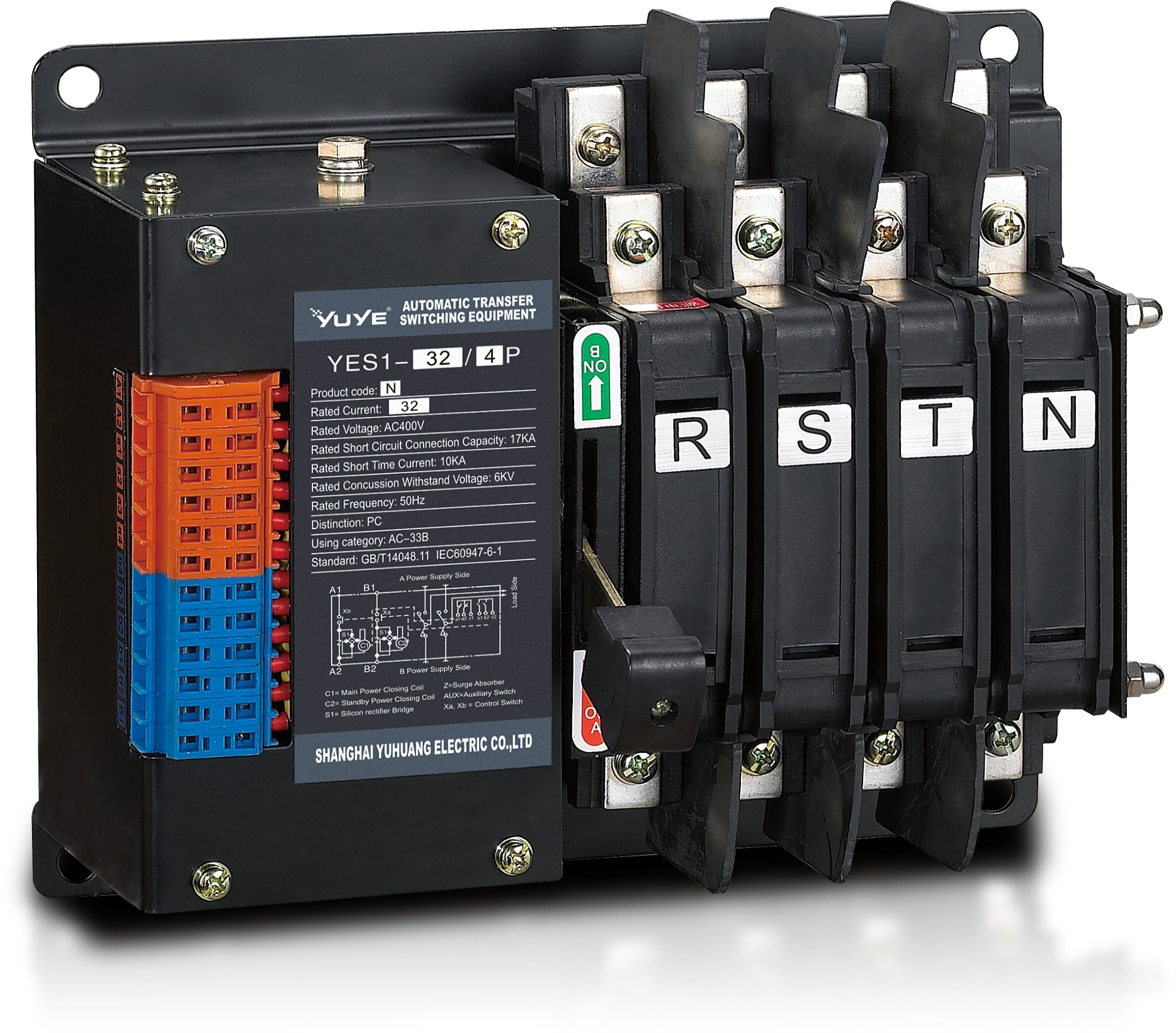
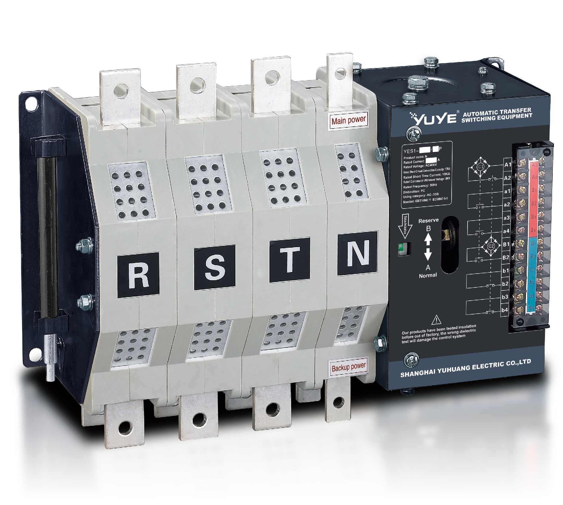
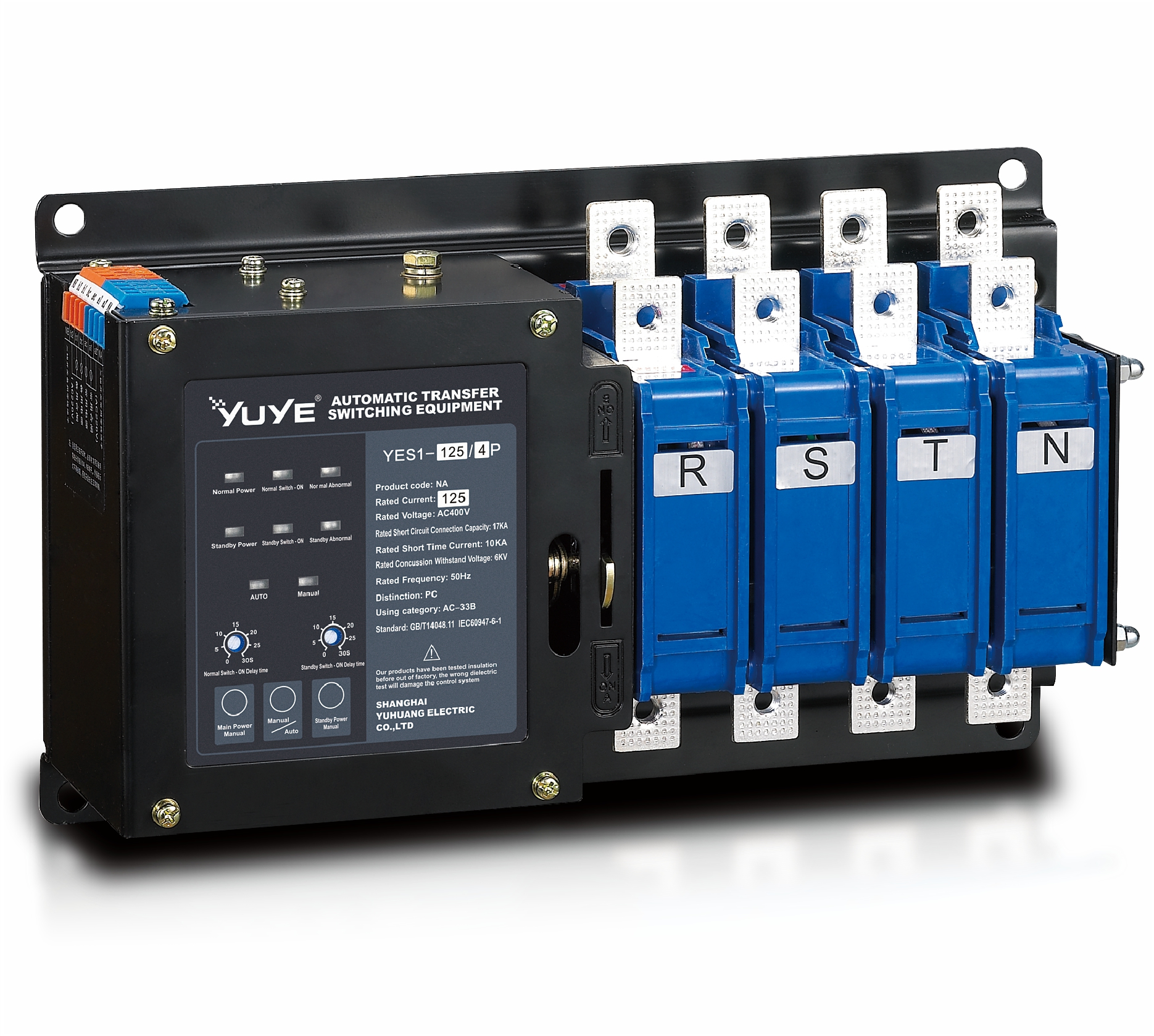
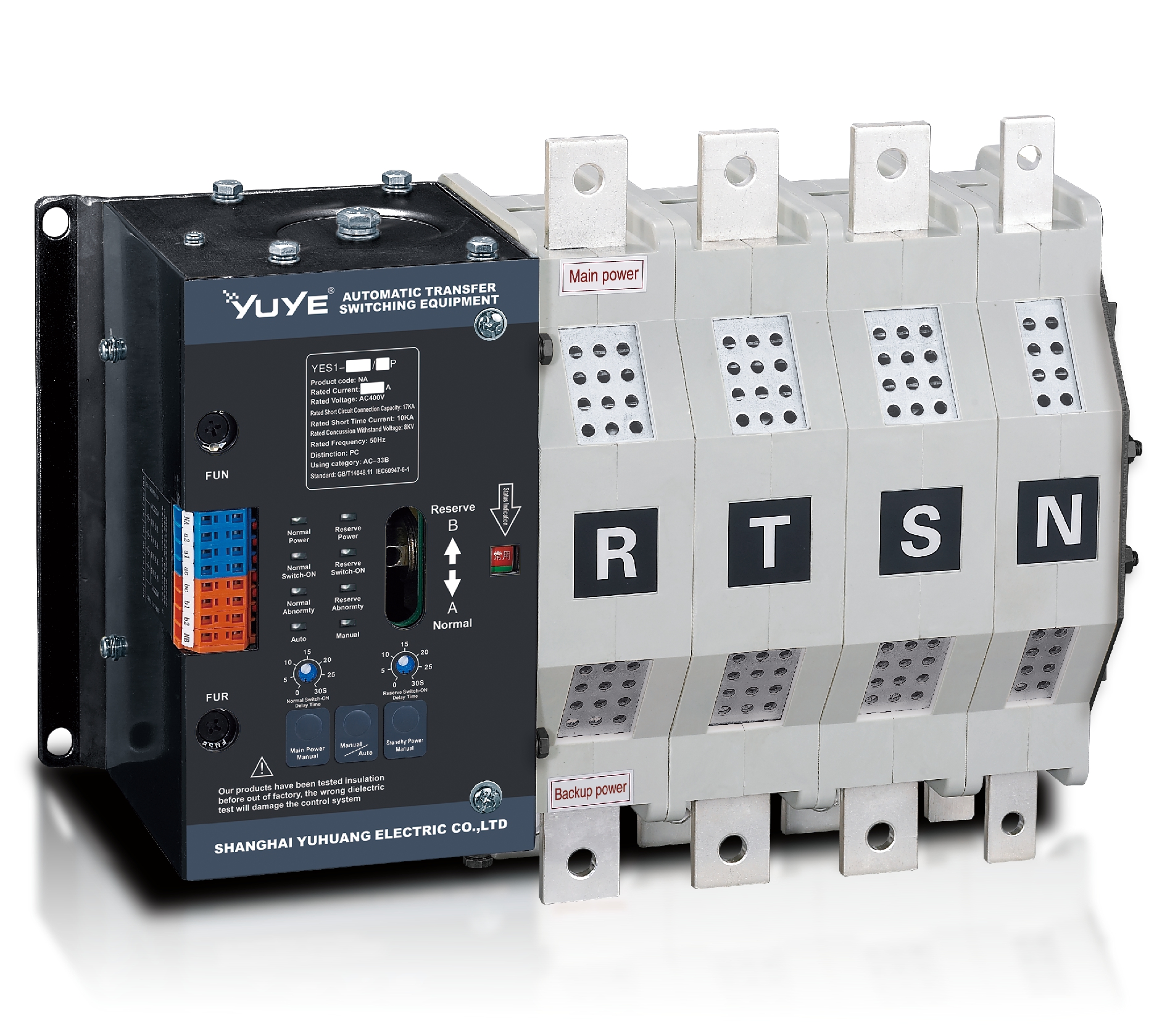
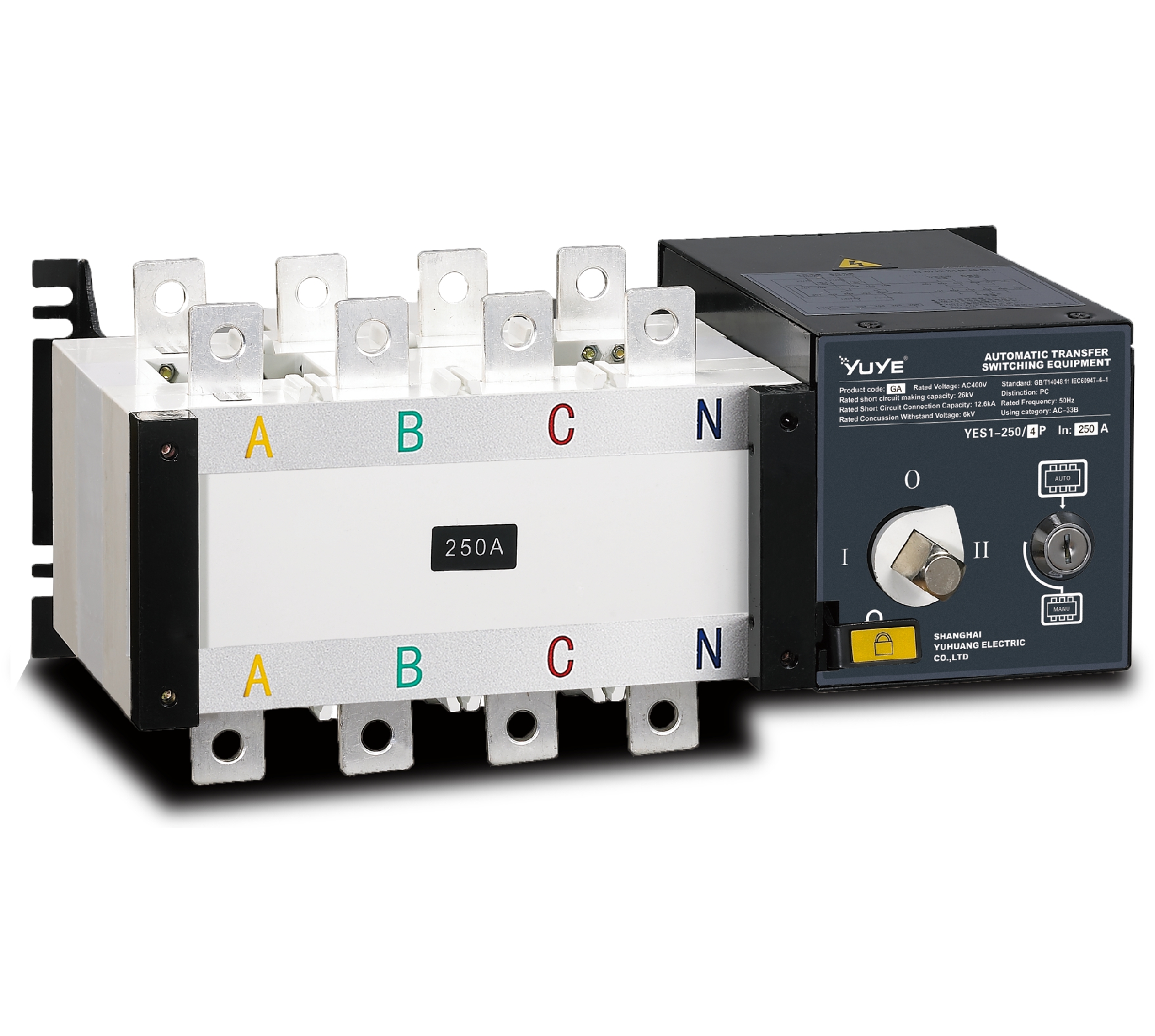
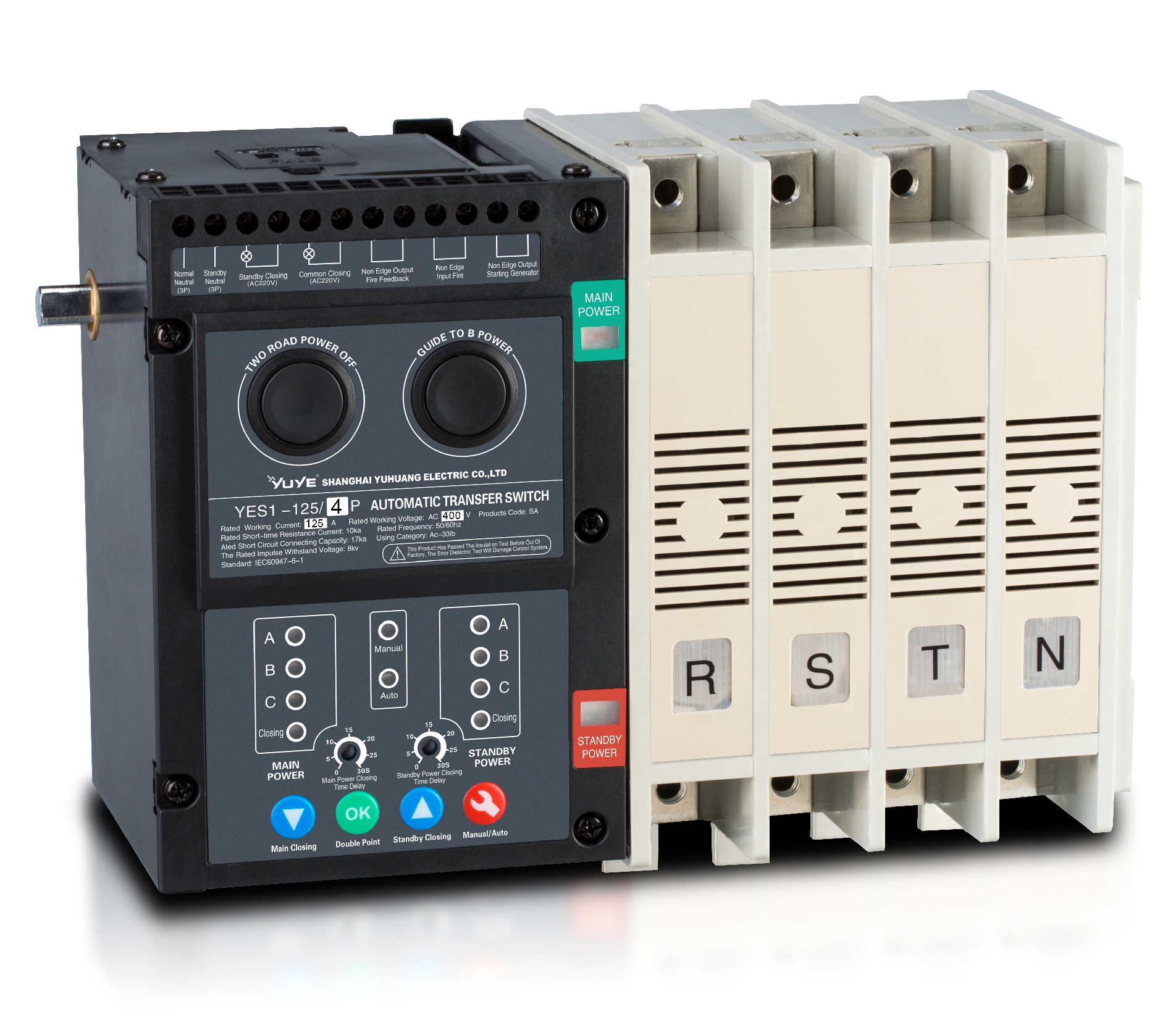
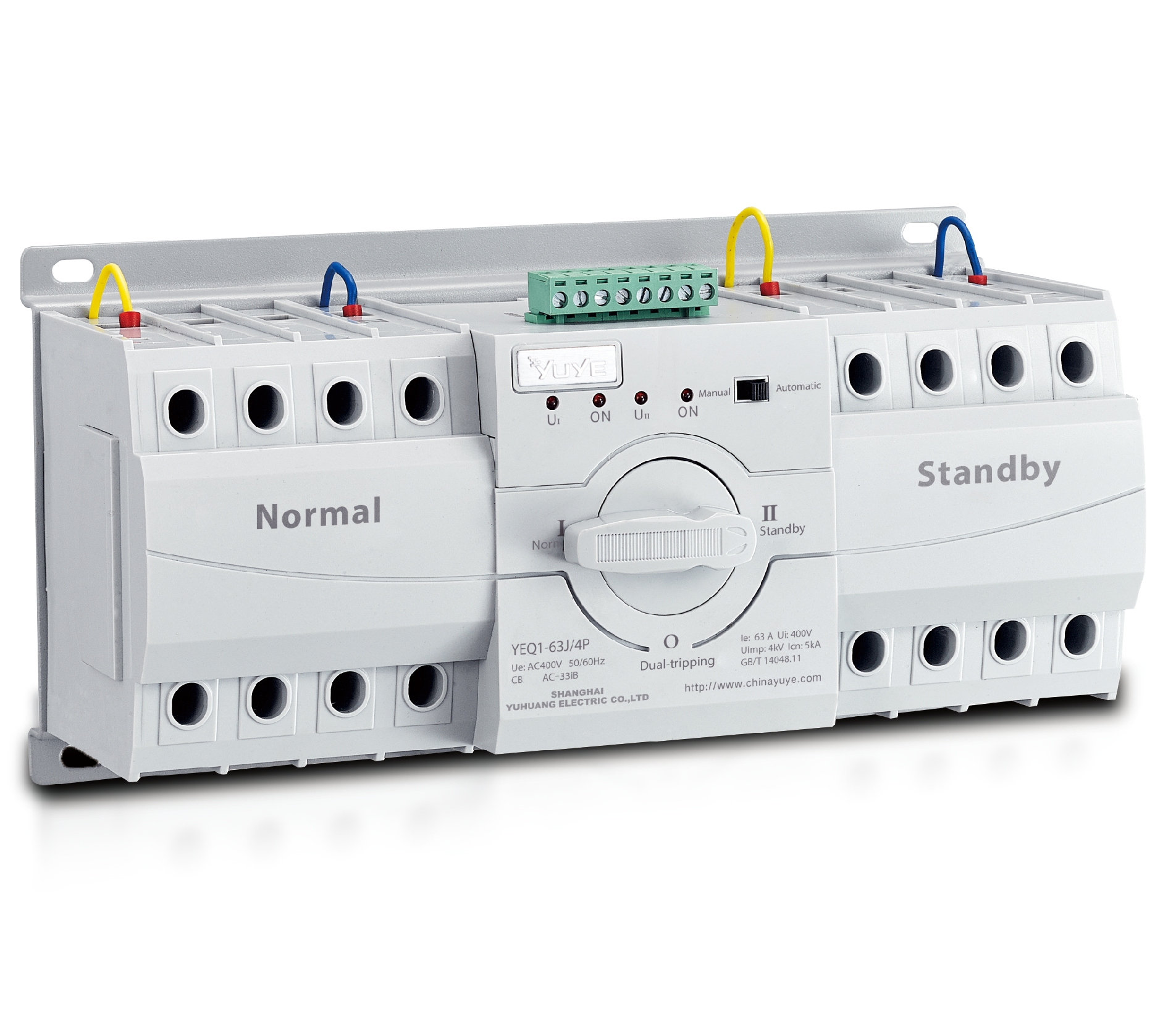
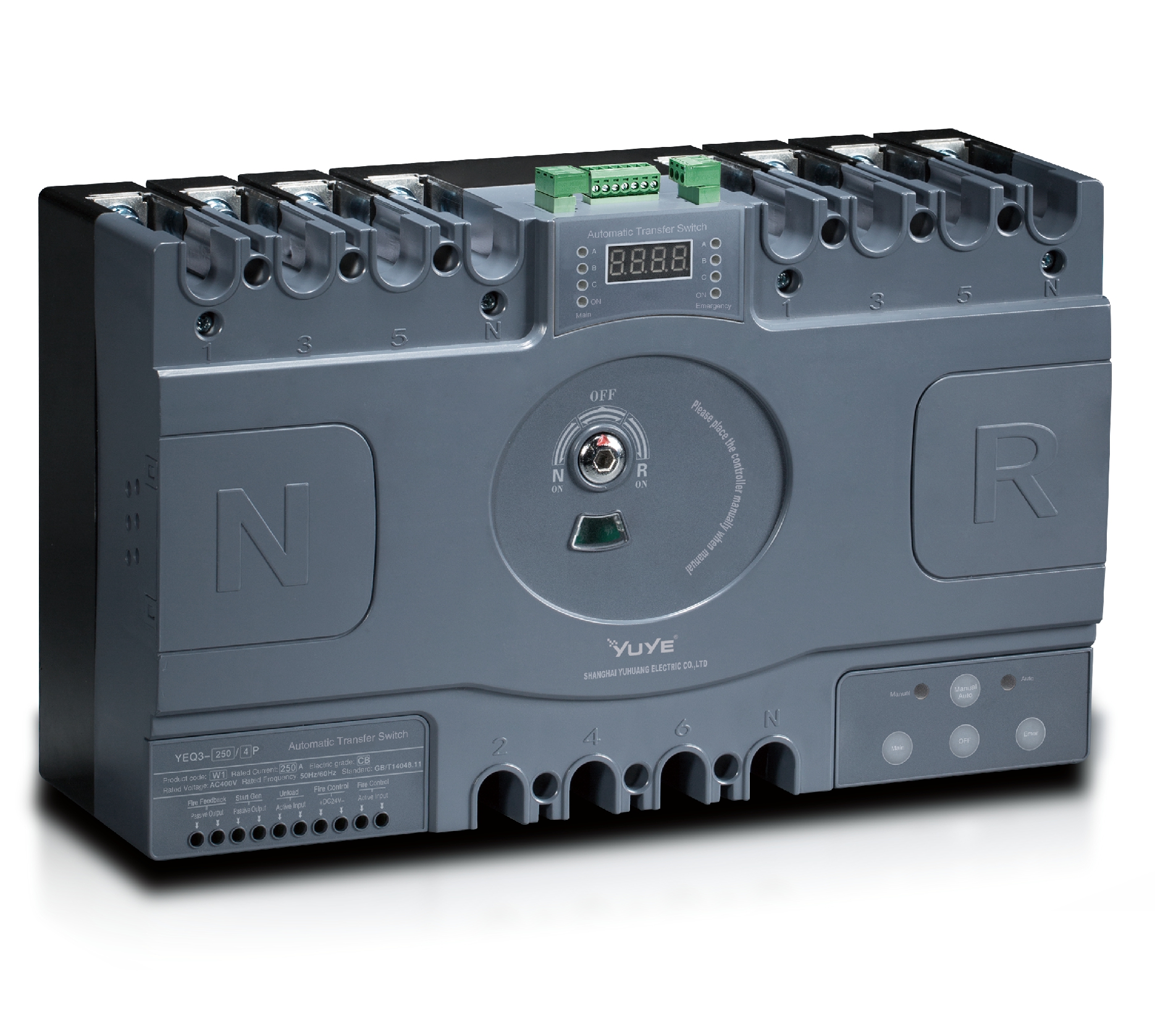
A dual power automatic transfer switch monitors two electrical sources and moves a load between them. Usually, one source is normal utility power, while the other is a generator or independent feeder. Its role is not merely to “change wires.” It senses voltage, frequency, phase conditions, and source availability before switching. When utility power fails, the controller can start the standby generator and transfer selected circuits after a programmed delay. This protects pumps, medical equipment, control panels, and emergency lighting from sudden interruptions.

During site inspections, technicians often check the switch beside a generator, with labeled cables entering from above and outgoing circuits leaving below. The enclosure must suit the installation environment, including heat, moisture, dust, and available space. Check the continuous current rating, short-circuit withstand rating, number of poles, and whether the neutral must be switched. A poor neutral arrangement can create unwanted circulating current or unstable equipment operation. That detail is easy to miss.

The switch should also prevent both sources from connecting together accidentally. Break-before-make operation is common, although some critical systems require carefully engineered closed-transition equipment. Adjustable delays reduce nuisance transfers caused by brief voltage dips. Maintenance records should show contact inspections, insulation checks, manual-transfer tests, and battery condition. Testing under realistic load is better than pressing a test button once. Still, specifications can be imperfect, and site conditions may expose assumptions made during design. Have a qualified electrical professional verify coordination, grounding, protection settings, and local code requirements before installation.

Identify the Required Power Sources and Load Capacity

How to Choose a Dual Power Automatic Transfer Switch?

Identify the Required Power Sources and Load Capacity

Start by identifying both power sources clearly. Common arrangements include utility power and a standby generator. Check their voltage, phase, frequency, and grounding arrangement. These details must match the transfer switch specifications. A mismatch can create nuisance trips or unsafe switching.

Then calculate the connected load. List lighting, pumps, heating equipment, controls, and sensitive electronics separately. Do not rely only on the main breaker rating. Motors may draw several times their running current during startup. Refrigeration compressors and pumps often expose this mistake quickly. Include the largest starting load and any loads that operate simultaneously. Leave reasonable capacity for future equipment. Too much spare capacity, however, can increase cost without improving performance.

An experienced electrician should verify the calculation at the installation site. Measure actual current when practical. Review the generator’s continuous output, not only its short-term rating. Confirm whether the system requires switched neutral operation. Also check available fault current and enclosure conditions. A dusty plant room needs different protection than a clean indoor cabinet. Installation manuals and local electrical codes remain essential references. I have seen projects fail because a small auxiliary load was forgotten. Rechecking the list feels slow, but it prevents expensive changes later. Avoid assuming that a larger switch automatically provides better protection.

Compare Transfer Switch Types and Operating Mechanisms

How to Choose a Dual Power Automatic Transfer Switch?

A dual power automatic transfer switch connects a primary source with a standby source. Its controller monitors voltage, frequency, and phase. When the preferred supply fails, the switch transfers the load automatically. Open-transition models briefly disconnect both sources. This prevents source paralleling but creates a short interruption. Closed-transition models overlap sources for milliseconds, reducing transfer disturbance. They require tighter synchronization and more complex protection.

Switching speed matters, but it is not the only measure. A hospital imaging room may need a fast, break-before-make transfer. A server room may favor closed transition, if the utility and generator support synchronization. IEC 60947-6-1 provides a recognized framework for transfer switching equipment. Site testing still matters more than a brochure claim. Watch the contacts move. Check the neutral. Record the actual transfer time.

The Uptime Institute’s 2024 Global Data Center Survey indicates that roughly three in ten reported outages cost at least $100,000. Meanwhile, the IEA’s Electricity 2024 report projects data-center electricity demand could exceed 1,000 TWh by 2026. These figures make source reliability a practical design issue. Choose a mechanically interlocked or electrically interlocked design after reviewing fault levels, load type, and maintenance access. Do not assume the largest rating is safest. A poorly coordinated switch can delay recovery. That detail is easy to miss.

Evaluate Safety Features, Controls, and Switching Speed

Choosing a dual power automatic transfer switch starts with the load, not the product label. In field inspections, I look for stable sensing before impressive specifications. The switch should monitor voltage, frequency, phase loss, and abnormal phase sequence. It must prevent both power sources from connecting at once. That interlock matters. Mechanical and electrical interlocking provide stronger protection than software logic alone. Check short-circuit ratings, enclosure protection, grounding provisions, and compliance with applicable electrical standards.

Controls determine how predictably the switch behaves during faults and maintenance. Look for adjustable undervoltage, overvoltage, transfer, and return-to-normal delays. A manual test position lets technicians simulate source failure without interrupting every building circuit. Clear indicators should show source availability, switch position, and alarm history. Remote signals are useful, but they should not replace local inspection. I have seen confusing labels slow troubleshooting in noisy, poorly lit rooms. That detail is easy to overlook.

Switching speed must match load sensitivity, not marketing claims. A generator may need a start delay, while medical or data loads may require fast transfer or UPS support. Measure actual transfer time under realistic voltage and frequency conditions. Ask whether published figures exclude sensing, generator starting, or stabilization delays. Faster is not always safer. An overly aggressive setting can cause nuisance transfers and unnecessary wear. Record test results, inspect terminals for heat marks, and review maintenance records before approval. I would also leave reasonable timing margins, because real systems rarely behave like laboratory demonstrations.

How to Choose a Dual Power Automatic Transfer Switch? - Evaluate Safety Features, Controls, and Switching Speed
Evaluation Dimension What to Evaluate Typical Benchmark or Target Why It Matters How to Verify
Rated Current Continuous current rating of the transfer switch and compatibility with the connected load, feeder, and protective devices. Select a rating equal to or higher than the calculated continuous load. Common low-voltage applications use ratings from approximately 30 A to 4,000 A. Underrating can cause overheating, nuisance trips, contact damage, or premature failure. Compare the nameplate rating with the design current, conductor ampacity, and upstream protection.
System Voltage and Frequency Compatibility with the nominal line-to-line or line-to-neutral voltage and system frequency. Typical low-voltage systems are 120/208 V, 120/240 V, 277/480 V, or similar at 50 or 60 Hz. Incorrect voltage or frequency settings may prevent transfer or damage connected equipment. Confirm the switch rating, wiring diagram, phase configuration, and controller settings.
Standards and Certification Evidence that the complete assembly has been tested to the standards required by the installation location. Common references include UL 1008 for transfer-switch equipment and IEC 60947-6-1 for transfer switching equipment, subject to local requirements. Unverified equipment may have inadequate short-circuit, endurance, insulation, or temperature performance. Request current certification documents, test ratings, and the exact model configuration.
Short-Circuit Withstand Short-circuit withstand and closing ratings, including the available fault current at the installation point. The transfer switch short-circuit rating must be equal to or greater than the available fault current. Values vary by voltage, frame size, and protective-device combination. Insufficient fault withstand can result in catastrophic equipment damage and loss of isolation. Obtain the calculated available fault current and compare it with the tested rating shown in the certification documentation.
Neutral Switching Whether the neutral is solid, switched, or switched with overlapping or non-overlapping contact operation. A switched neutral may be required where separately derived sources, generator grounding, or local electrical rules require source separation. An unsuitable neutral arrangement can create objectionable current, grounding conflicts, or unsafe fault-current paths. Review the grounding design with a qualified electrical professional and confirm the number of poles in the transfer switch.
Source Monitoring Monitoring of source voltage, frequency, phase loss, phase sequence, undervoltage, and overvoltage. Adjustable undervoltage and overvoltage thresholds are commonly provided; typical undervoltage pickup settings may be around 80% to 95% of nominal voltage, depending on the application. Poor monitoring can transfer loads to an unstable source or fail to transfer when the preferred source is unavailable. Check sensing accuracy, adjustable thresholds, time delays, and the number of monitored phases.
Transfer and Retransfer Delays Time delays before starting the alternate source, transferring the load, and returning to the preferred source. Adjustable delays commonly range from seconds to several minutes. A short emergency transfer delay may be used for critical loads, while retransfer is often intentionally delayed to confirm source stability. Delays that are too short may cause nuisance transfers; delays that are too long may interrupt critical operations. Confirm default and adjustable settings, timing tolerance, and the required sequence for the facility.
Switching Speed Actual mechanical transfer time after the controller issues a transfer command, excluding source-start and programmed time delays. Open-transition devices commonly complete the mechanical transfer in a fraction of a second to several seconds, depending on frame size and mechanism. The total interruption is determined by sensing, source availability, delays, and switching time. A fast mechanism alone does not guarantee uninterrupted power; sensitive loads may still require a UPS or other power-conditioning system. Request timing data measured under rated conditions and test the complete transfer sequence with the intended sources.
Transition Type Whether the unit uses open transition, closed transition, or delayed transition switching. Open transition briefly disconnects the load from both sources. Closed transition momentarily parallels sources and requires compatible, synchronized sources. Delayed transition provides a programmed neutral or disconnected interval. The wrong transition type can cause unacceptable interruptions, source paralleling, inrush problems, or coordination issues. Match the transition method to utility rules, generator capability, load sensitivity, and protection coordination.
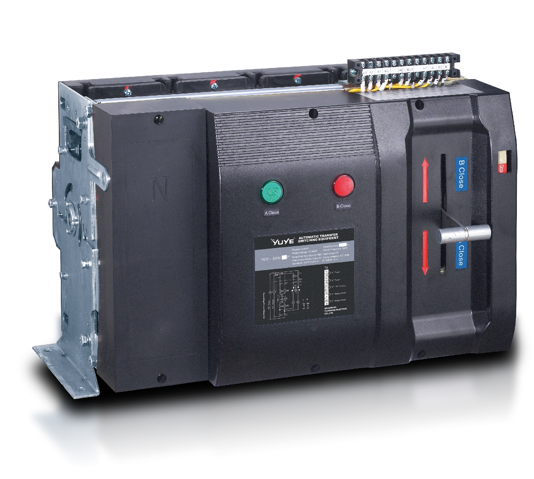
Manual Operation and Interlocking Availability of a safe manual operating handle, electrical interlocks, mechanical interlocks, and a clear emergency operating procedure. The mechanism should prevent both sources from being unintentionally connected in an open-transition configuration and should provide a defined manual or test position. Inadequate interlocking can lead to accidental source paralleling, arc-flash exposure, or unsafe maintenance conditions. Inspect the mechanism, interlock logic, lockout provisions, and documented operating instructions.
Control Power and Fail-Safe Behavior Control-power source, ride-through capability, behavior after controller failure, and position indication during loss of control power. The controller should have defined behavior for loss of sensing or control power and should provide reliable source and switch-position indication. Unclear fail-safe behavior may leave the load disconnected or make the actual switch position uncertain. Review the control schematic and perform loss-of-control-power and abnormal-condition tests.
Generator Start Interface Two-wire start contacts, engine warm-up coordination, cooldown timing, and compatibility with the generator controller. The ATS should provide clearly defined dry contacts or an approved communication interface and adjustable start, transfer, retransfer, and cooldown sequences. Incorrect signaling can cause delayed emergency power, repeated generator starts, or premature shutdown. Test the complete generator-ATS sequence under simulated utility failure and restoration.
Load Protection and Inrush Compatibility with motor starting current, transformer inrush, capacitive loads, and downstream circuit-breaker coordination. The switch and source should tolerate the expected inrush without nuisance operation; large motor or transformer loads may require staggered starting or delayed transfer. High inrush can cause voltage sag, failed transfer, nuisance trips, or generator instability. Review load-starting calculations and test the largest expected combined inrush condition.
Environmental and Enclosure Rating Ambient temperature, humidity, altitude, ventilation, corrosion exposure, seismic requirements, and enclosure protection. Common indoor enclosures may use NEMA 1 or IP-rated equivalents; outdoor or wet locations typically require a higher enclosure rating and suitable environmental construction. Environmental mismatch can reduce insulation performance, accelerate corrosion, and impair mechanism reliability. Compare the installation conditions with the enclosure rating, derating data, and environmental limitations.
Monitoring and Communications Local display, event history, alarms, remote status contacts, and communication interfaces for building-management or power-monitoring systems. Useful points include source availability, switch position, generator start status, transfer/retransfer events, test mode, and active alarms. Insufficient information can delay fault diagnosis and make preventive maintenance difficult. Confirm supported protocols, alarm contacts, event-log capacity, cybersecurity requirements, and data accuracy.
Testing and Maintenance Availability of automatic exercise, test-with-load or test-without-load functions, inspection points, replacement parts, and maintenance instructions. The system should support periodic functional testing and documented inspection of contacts, terminals, mechanism operation, sensing, and control settings. An untested ATS may fail during the first actual outage, even if normal operation appears satisfactory. Create a test schedule based on the facility risk profile and record transfer, retransfer, alarm, and source-start results.
Application Priority Criticality of the connected load, acceptable interruption duration, and consequences of transfer failure. Life-safety, emergency, data-processing, medical, and industrial loads may require different transfer logic, redundancy, bypass-isolation, or power-conditioning equipment. A standard ATS may not meet the continuity, maintenance, or fault-tolerance needs of highly critical loads. Define the required availability, maximum interruption, maintenance strategy, and applicable facility codes before selection.
Note: Benchmarks are representative engineering guidance rather than a substitute for the applicable electrical code, authority requirements, load study, or equipment-specific certification data.

Check Installation Conditions and System Compatibility

Choosing a dual power automatic transfer switch starts with the installation site, not the product catalogue. During site surveys, measure available space, cable bending radius, ambient temperature, dust, moisture, and ventilation. A cabinet beside a generator may face heat and vibration. An indoor enclosure rating will not suit that location. Check the protection rating against the actual environment, not an ideal one.

System compatibility requires careful electrical matching. Confirm nominal voltage, phase arrangement, frequency, rated current, short-circuit withstand capacity, and neutral switching requirements. The switch must coordinate with upstream breakers and downstream loads. Motor loads, medical equipment, and control systems can react badly to transfer delays or brief voltage loss. Verify whether the system needs open, delayed, or closed transition. Closed transition demands precise synchronisation and protection checks. Do not guess.

Installation quality also affects reliability. Inspect source terminals, earthing, cable size, control wiring, and generator start signals before energising the unit. Test both sources under realistic load, including manual bypass procedures where applicable. A wiring diagram may look clear, yet one reversed phase can create a serious fault. I have seen commissioning teams overlook neutral continuity because the cabinet looked correctly labelled. That mistake is avoidable, but field conditions are rarely perfect. Measure twice. Leave maintenance access, record test results, and have a qualified engineer verify the final settings.

Review Maintenance Needs, Standards, and Total Cost

How to Choose a Dual Power Automatic Transfer Switch?

A dual power automatic transfer switch should be judged beyond its purchase price. In field inspections, I have seen low-cost units create higher expenses through difficult testing and unavailable replacement parts. Review the switch’s transfer mechanism, controller access, contact life, and enclosure rating. Ask how often inspections are required and whether technicians can replace fuses, sensors, or control modules without removing the entire unit. Clear maintenance procedures reduce downtime during power failures.

Standards also affect long-term reliability. Check compliance with applicable requirements, such as IEC 60947-6-1, NFPA 110, and local electrical codes. Requirements vary by installation and region. Confirm testing records, short-circuit ratings, switching categories, and emergency-power compatibility. A certificate alone is not enough. Review the actual test scope and installation conditions. This step is often overlooked.

Tips:

Compare total cost over ten years, not only the initial quotation. Include commissioning, inspections, spare parts, energy losses, training, and possible shutdown time. Choose accessible terminals and readable status indicators. They save minutes. Also, question optimistic maintenance claims. Real sites are dusty, humid, and occasionally neglected. A switch designed for perfect conditions may fail when routines slip. I would rather select a slightly simpler unit with documented service support than an advanced model that local technicians cannot maintain.

ATS Controller Y-700: Reliable Automatic Transfer for Critical Power Systems

The ATS Controller Y-700 is designed for reliable automatic transfer in critical power systems where continuity and stable control are essential. It can operate from a constant DC supply ranging from 8.0V to 35.0V, while compatible power module supplies can also be used without battery charging. For applicable versions, including Y-700/B and Y-700/BI, the controller can be powered through AC L1N1 or L2N2 inputs within a 160–280V range at 50/60Hz. Its low power consumption, below 3W and no more than 2W in standby mode, supports efficient long-term operation.

The unit provides a 16A, 250V AC free-voltage relay output for close and open trip control, along with a programmable relay output rated at 16A/7A, 250V AC. These flexible outputs help integrate the controller with transfer mechanisms, alarms, and other power-management equipment. Digital inputs are activated by connecting them to ground, simplifying connection to external status or control signals. For monitoring and system integration, the Y-700 includes RS485 communication with the MODBUS protocol, enabling data exchange with supervisory equipment and supporting practical control in generators, backup power installations, and other critical electrical applications.

FAQS

What does a dual power automatic transfer switch do?

It monitors two electrical sources and moves selected loads between them. One source is usually utility power. The other may be a generator or independent feeder. It checks voltage, frequency, phase, and availability before switching.

What happens when normal power fails?

The controller can start the standby generator. After a programmed delay, it transfers selected circuits. This helps protect pumps, medical equipment, control panels, and emergency lighting. Timing matters.

Which electrical details must match?

Confirm voltage, phase, frequency, and grounding arrangements for both sources. The switch specifications must suit these values. A mismatch may cause nuisance trips or unstable operation.

How should load capacity be calculated?

List lighting, pumps, heating equipment, controls, and sensitive electronics separately. Include loads operating at the same time. Motor starting current can be several times its running current. Do not use only the main breaker rating. A neat calculation can still be wrong.

Why are motor starting loads important?

Pumps and refrigeration compressors can demand sharp starting current. A switch or generator sized only for running current may struggle. Measure actual current when practical. Small omissions become expensive.

What enclosure conditions should be considered?

Check heat, moisture, dust, available space, and installation access. A dusty plant room may need different protection than a clean indoor cabinet. Labeled cables should enter and leave without crowding.

Should the neutral be switched?

That depends on the grounding arrangement and system design. A qualified electrical professional should verify it. A poor neutral arrangement can cause circulating current or unstable equipment operation. This detail is easy to miss.

How does the switch prevent unsafe source connection?

It should prevent both sources from connecting together accidentally. Break-before-make operation is common. Some critical systems need engineered closed-transition equipment. The choice requires careful coordination.

How should the transfer switch be tested and maintained?

Records should include contact inspections, insulation checks, manual-transfer tests, and battery condition. Test under realistic load when possible. Pressing a test button once is not enough. Site conditions can expose design assumptions.

Conclusion

Choosing the right Dual Power Automatic Transfer Switch begins with understanding its role: it automatically changes a critical load from the primary power source to a backup source when an interruption or voltage problem occurs. Start by identifying the available power sources, voltage, phase configuration, frequency, and the total load capacity, including motor starting currents and future expansion. These details help ensure the switch is correctly rated and suitable for the intended application.

Next, compare switch types and operating mechanisms, such as open, closed, or delayed transition, according to the required continuity and equipment sensitivity. Evaluate safety features, manual controls, monitoring functions, interlocks, and transfer speed. Installation conditions, enclosure protection, wiring space, environmental exposure, and compatibility with generators or other backup systems should also be checked. Finally, consider testing and maintenance requirements, applicable electrical standards, expected service life, energy efficiency, and the total cost of ownership. A well-matched switch should provide reliable operation, safe power transfer, and practical long-term maintenance.

Blog Tags:

Noah

Noah

Noah is a dedicated marketing professional at One Two Three Electric Co., Ltd., a distinguished manufacturer renowned for its high standards in the development and production of molded case circuit breakers and air circuit breakers. With a profound expertise in electrical solutions, Noah......
Previous What Is an Automatic Transfer Switch?
Click For Inquiry