PC ATS YECT1-2000G
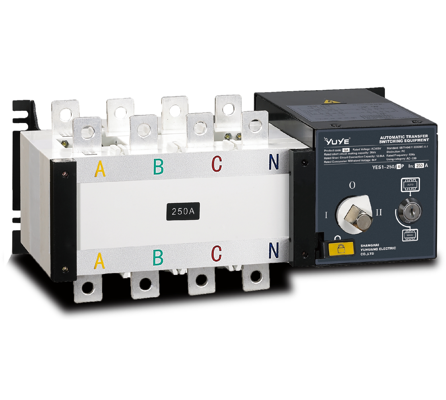
PC ATS YES2-63~250GN1
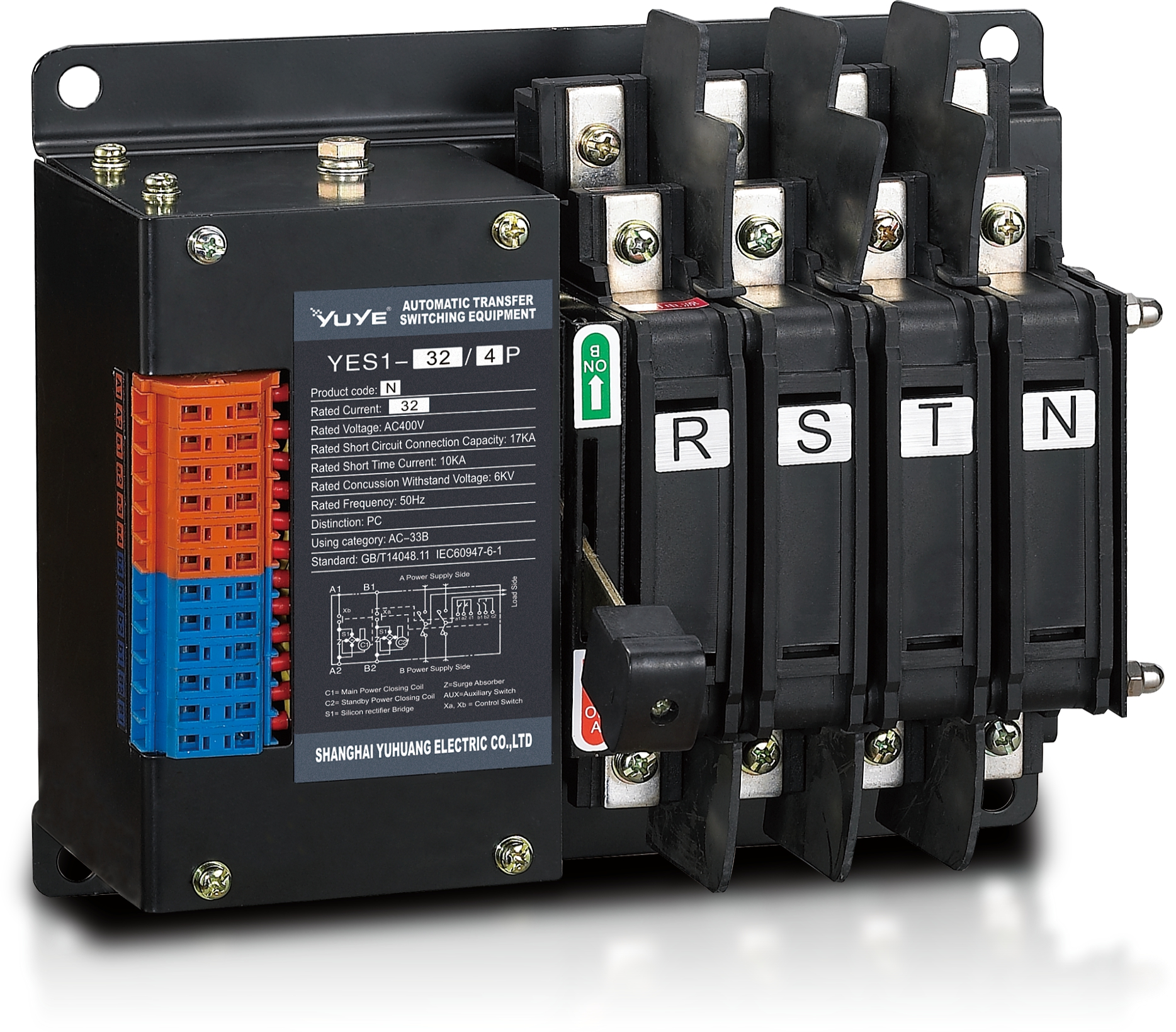
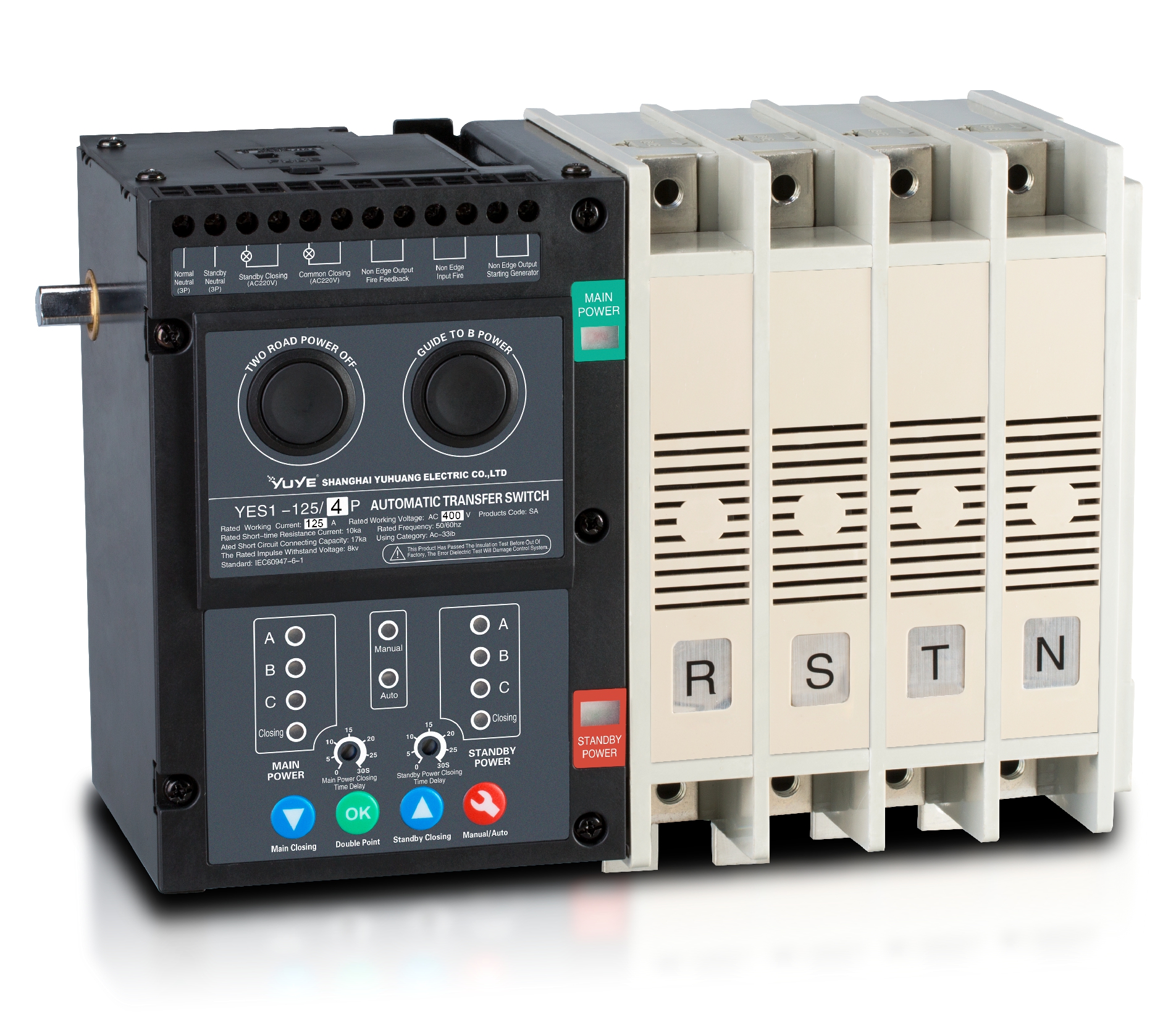
Solenoid-type ATS YES1-32~125N
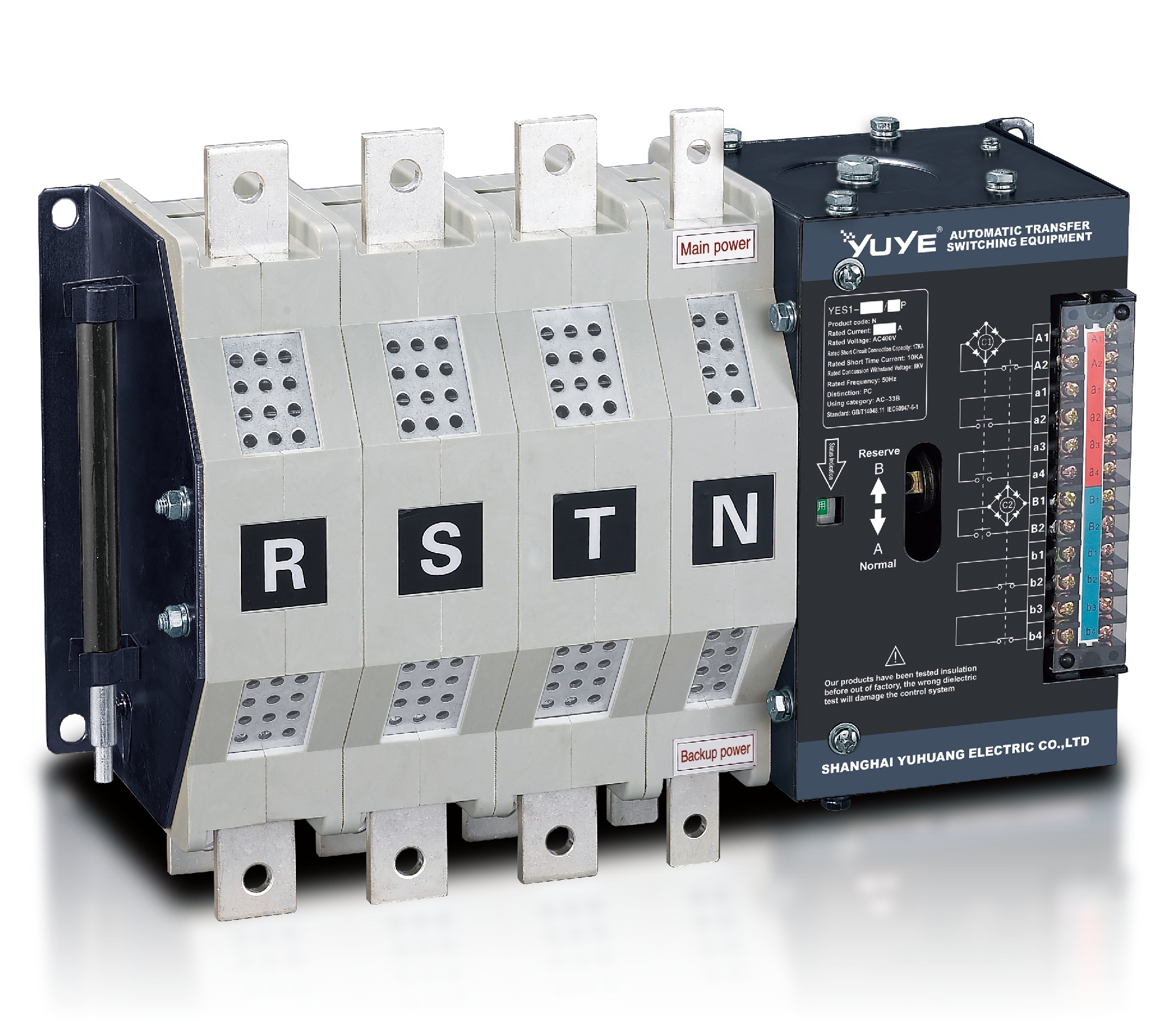
Solenoid-type ATS YES1-250~630N/NT
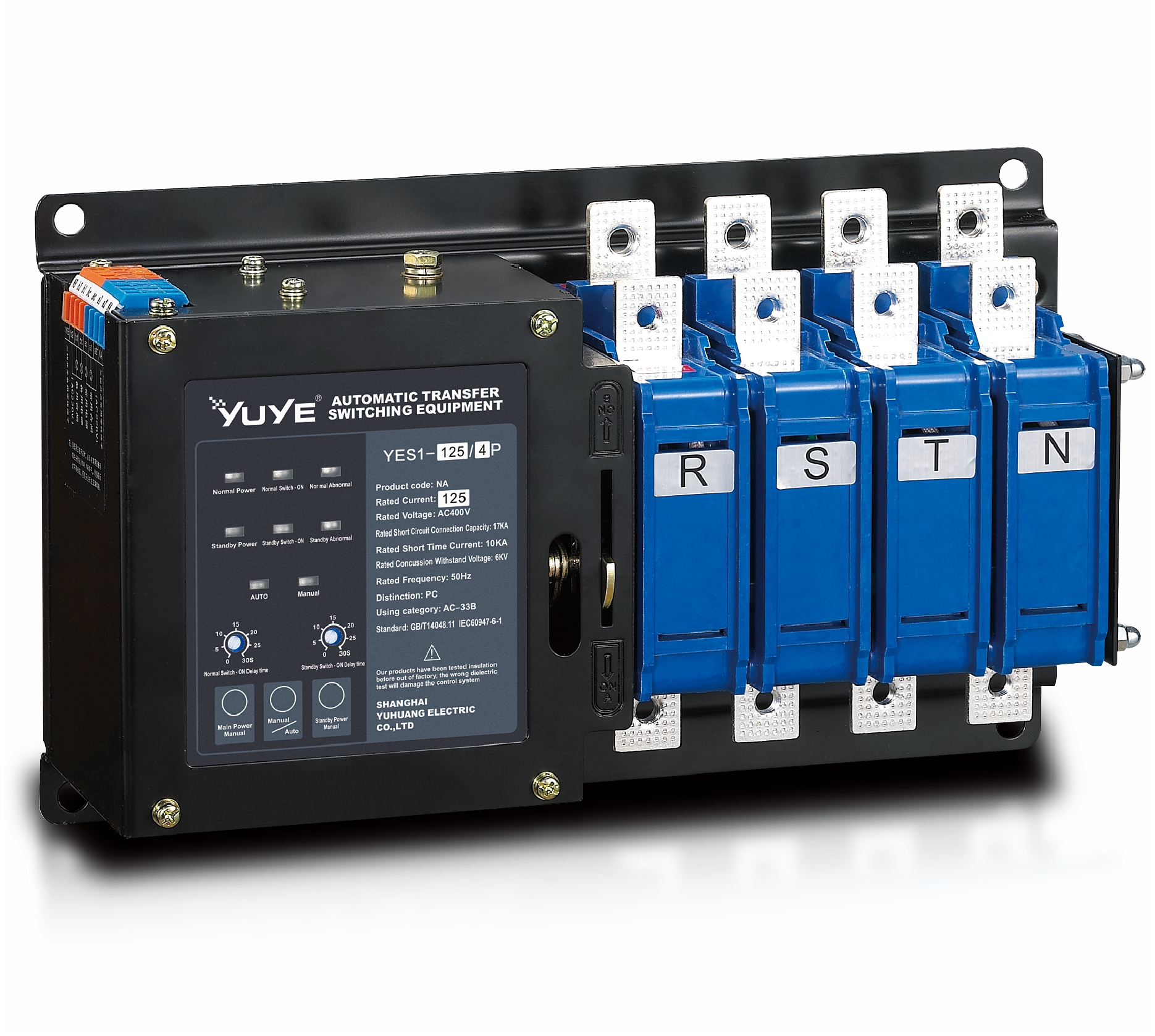
Solenoid-type ATS YES1-32~125NA
Solenoid-type ATS YES1-63~630SN
Solenoid-type ATS YES1-1250~4000SN
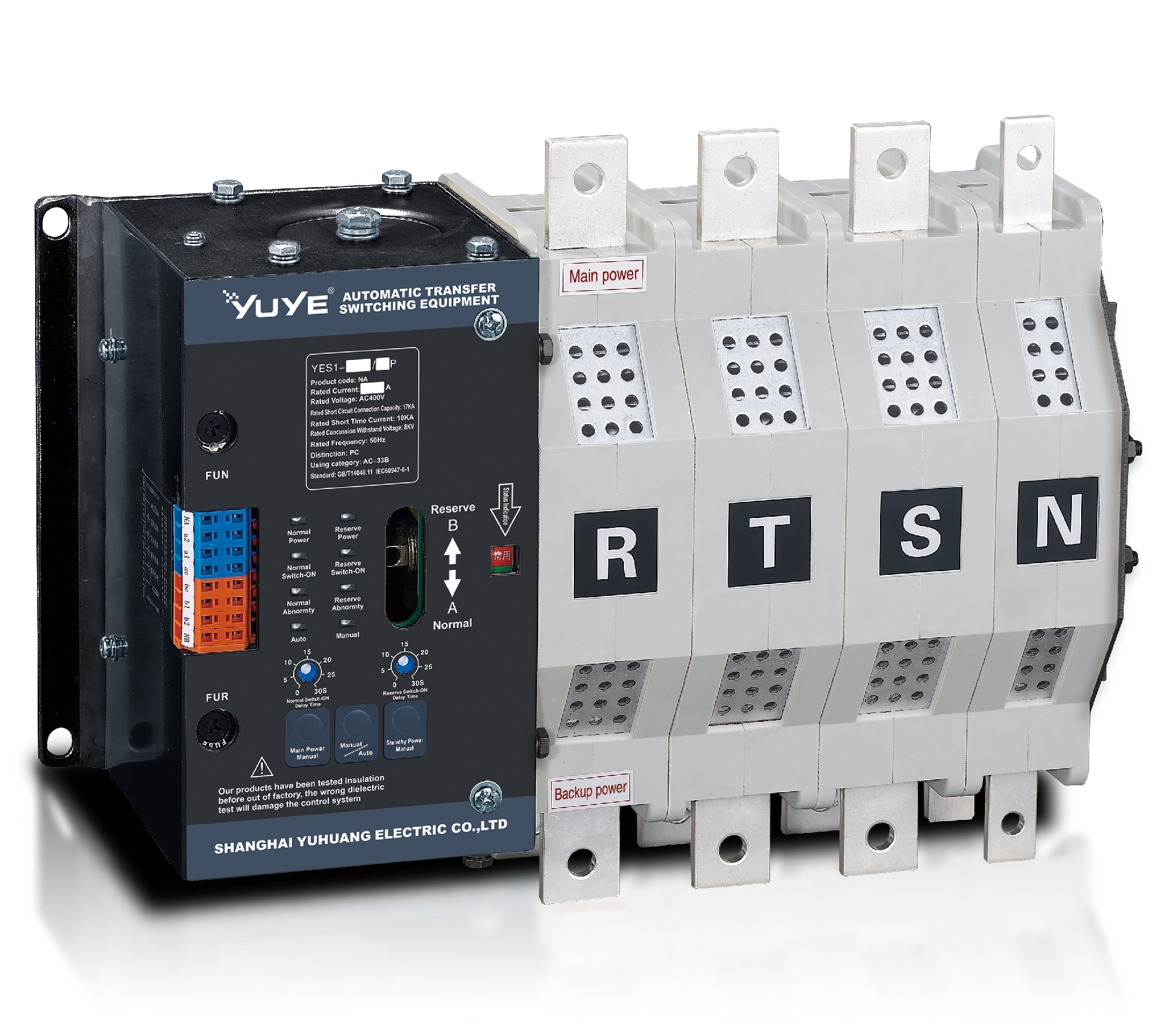
Solenoid-type ATS YES1-250~630NA/NAT
Solenoid-type ATS YES1-63NJT
PC ATS YES1-100~1600GN1/GN/GNF
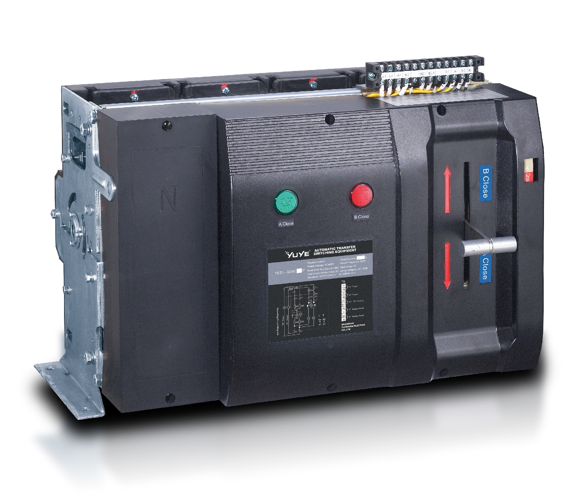
PC ATS YES1-2000~3200GN/GNF
PC ATS YES1-100~3200GA1/GA
Solenoid-type ATS YES1-63~630SA
Solenoid-type ATS YES1-63~630L/LA
Solenoid-type ATS YES1-63~630LA3
Solenoid-type ATS YES1-63MA
PC ATS YES1-630~1600M
PC ATS YES1-3200Q
Solenoid-type ATS YES1-4000~6300Q
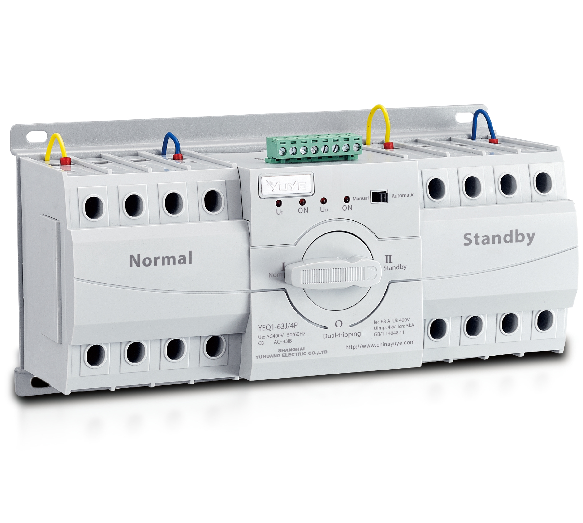
CB ATS YEQ1-63J
CB ATS YEQ2Y-63
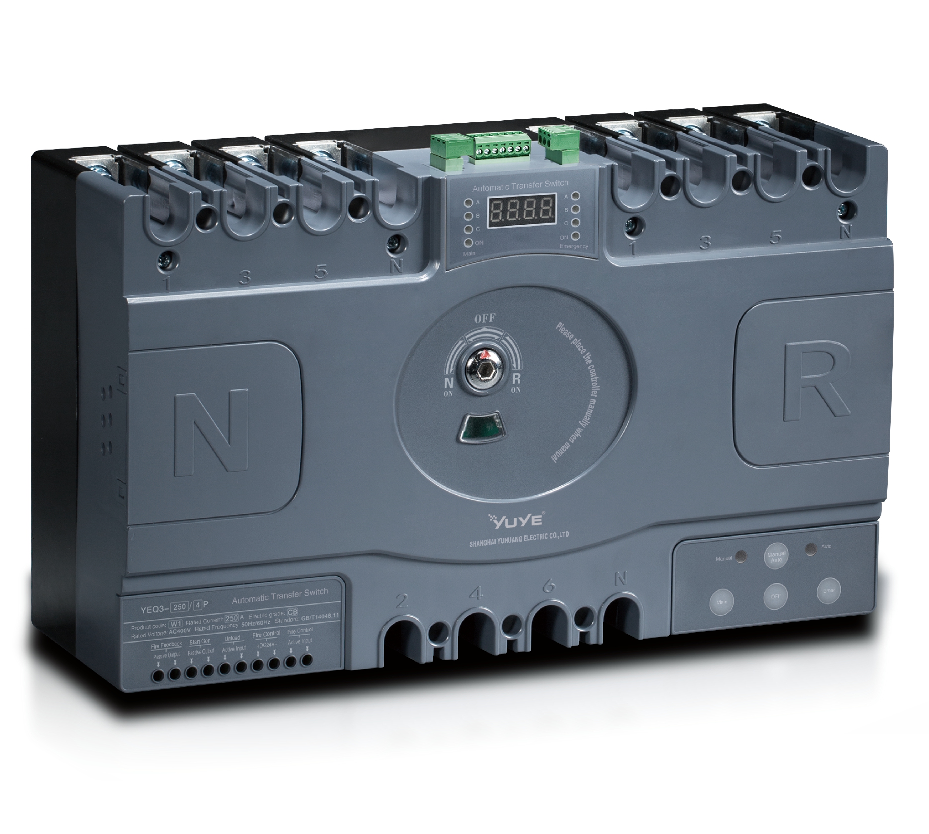
CB ATS YEQ3-63W1
CB ATS YEQ3-125~630W1
ATS controller Y-700
ATS Controller Y-700N
ATS Controller Y-701B
ATS Controller Y-703N
ATS Controller Y-800
ATS Controller W2/W3 Series
ATS switch Cabinet floor-to-ceiling
ATS switch cabinet
JXF-225A power Cbinet
JXF-800A power CbinetChoosing the right Automatic Transfer Switch (ATS) particularly a 630A model isn’t just about comparing prices, enclosure sizes, or how fast they switch over. Honestly, depending on what you’re protecting—say, a hospital wing, a data center, a factory line, or a big commercial building—you need to think about more than just specs. Things like voltage levels, phase configurations, neutral switching options, short-circuit ratings, and compatibility with your generator are all super important. Even small details matter — a loose cable lug can cause heat buildup, and a controller that's not quite right might delay your power restoration when you really need it.
When you're shopping around, it’s wise to start with some solid, verified technical info and practical experience. Look for clear test reports, trusted certifications, factory inspection records, and a good service plan backed by skilled technicians. The switch should perform reliably in simulated failure tests—think utility outages, generator start-ups, and switching back to mains. Features like manual operation, bypass isolation, alarm contacts, and how visible and accessible the controller is can really affect how safe and easy it is to maintain. Don’t just get dazzled by flashy claims — ask questions. How does it handle continuous loads? What's the procedure to get spare parts? And can local engineers handle the installation and commissioning without headaches?
Here’s the thing—there's no one-size-fits-all ‘best’ model. That’s the tricky part. An ATS built for a data center might totally flop in a dusty manufacturing plant. The quality of installation can be just as important as the brand itself. So, it’s a balancing act—consider the electrical performance, how well it stands up in harsh environments, the total cost over its lifespan, and of course, how reliable it’s proven to be. This guide aims to walk you through those points, helping you find a 630A transfer switch that actually fits your real-world needs—not just what looks good on a spec sheet.
A 630A automatic transfer switch (ATS) is a power-switching device designed to handle loads up to 630 amperes. It monitors two power sources, usually utility and standby power. When the main source fails, the ATS starts or signals the generator, then transfers the load after a programmed delay. When utility power becomes stable, it transfers the load back. The process is automatic, but not instantaneous.
A 630A ATS commonly serves large commercial buildings, industrial panels, data facilities, and essential electrical systems. Its enclosure contains switching contacts, a control module, sensing circuits, and mechanical or electrical interlocking. These parts prevent both power sources from connecting at the same time. Copper busbars, insulation, ventilation, and terminal spacing also affect safe operation. A 630A label alone does not prove suitability. Voltage, phase, frequency, short-circuit withstand rating, and applicable standards must also match the installation.
Selection should consider neutral switching, bypass isolation, emergency-load type, and maintenance access. Motor-driven equipment needs special attention because starting current can exceed running current. In practical panel rooms, cable bending space and heat matter as much as the nameplate. Testing should simulate source loss and restoration under controlled conditions. Torque records and inspection schedules improve reliability.
One point deserves reflection: even the best ATS cannot compensate for poor upstream protection or neglected maintenance.
What Is the Best Automatic Transfer Switch ATS 630A?
The answer depends on how reliably it handles a real power failure. A 630A ATS monitors the normal supply through voltage and phase sensors. When voltage drops beyond its set limit, the controller starts the standby generator or waits for an available backup source. The delay prevents transfer during brief voltage dips. That small pause matters.
After the backup source stabilizes, motor-driven contacts move from the normal position to the emergency position. Mechanical and electrical interlocks prevent both sources from connecting together. This protects the distribution system from dangerous back-feeding. In a properly adjusted unit, the load may experience only a short interruption. Sensitive equipment can still restart unexpectedly, however. That weakness is often overlooked.
During commissioning, technicians should test loss of one phase, undervoltage, frequency instability, and generator failure. A 630A rating describes current capacity, not complete system suitability. Cable size, fault protection, enclosure conditions, and neutral switching also require careful review.
I would record transfer time with a meter, not trust the display alone. Real measurements expose wiring mistakes. Monthly simulated outages can reveal weak batteries, loose terminals, or delayed generator response. The test may be inconvenient. Skipping it is worse.
A clear maintenance log helps operators identify changes before an emergency demands the switch.
A 630A automatic transfer switch should match the installation, not just the load rating. During site inspections, I check the system voltage, frequency, phase arrangement, and number of poles. The switch must handle the connected load continuously without excessive heat. Confirm whether 630A is the normal operating rating or only a short-duration limit. That detail is easy to miss.
Transfer time matters in hospitals, data rooms, and production lines. Ask for measured transfer and retransfer times, not broad marketing claims. Short-circuit withstand capacity is equally important. It should suit the available fault current and protective devices. Check the controller’s voltage and phase monitoring, adjustable delay settings, and generator start signal. Mechanical interlocking must prevent both sources from connecting together. Enclosure protection, terminal space, ventilation, and operating temperature also affect reliability. A compact cabinet may look efficient, but crowded wiring can complicate maintenance.
Tips: Request factory test records and a wiring diagram before purchase. Verify certification against the project’s required standards, such as IEC or UL requirements. Test manual operation, automatic transfer, and failure alarms during commissioning. Field conditions often differ from drawings. I have seen an otherwise suitable ATS fail because cable bending space was underestimated. Recheck that point.
What Is the Best Automatic Transfer Switch ATS 630A?
Types of 630A Automatic Transfer Switches
A 630A automatic transfer switch is selected by transfer behavior, fault level, and load type, not by amperage alone. The most common type is open-transition ATS. It disconnects the normal source before connecting the emergency source, creating a short interruption. This design suits pumps, lighting, and general commercial loads.
Closed-transition ATS briefly parallels both sources during transfer. It can reduce interruption, but engineers must verify synchronization, protection settings, and utility requirements. Delayed-transition ATS adds a programmed pause between sources, allowing motors and transformers to discharge. It is useful when residual voltage could cause inrush current. Some systems also use bypass-isolation construction, which lets technicians maintain the switching mechanism without shutting down critical loads. Practical experience shows this detail matters in hospitals and data rooms.
The switching mechanism may use molded-case, insulated-case, or power circuit breakers. Breaker-based designs often provide stronger fault withstand and easier coordination at 630A. Three-pole and four-pole versions must match the grounding system and neutral arrangement. IEC 60947-6-1 provides a key reference for transfer switching equipment, while NFPA 110 addresses emergency power performance. The IEA’s Electricity 2024 report estimates data-center electricity use could exceed 1,000 TWh globally by 2026. Reliability pressure is rising. Uptime Institute’s 2024 outage analysis also reported that many serious outages caused losses above $100,000. Still, selecting the largest ATS is not always wise. Short-circuit calculations, generator capacity, environmental temperature, and real load measurements should decide the final configuration. Mistakes happen when catalog ratings replace site testing.
| ATS Type | Basic Operating Principle | Typical Transfer Characteristics | Common Voltage and Pole Options | Suitable Applications | Main Advantages | Important Considerations | Relevant Standards and Selection Criteria |
|---|---|---|---|---|---|---|---|
| Open-Transition ATS | Disconnects the normal power source before connecting the emergency source. The load experiences a short interruption during transfer. | Typical transfer time is approximately 0.5 to 30 seconds, depending on source monitoring, generator start-up, and programmed delays. The switching mechanism itself generally operates within fractions of a second. | 630 A; commonly available in 3-pole or 4-pole configurations for low-voltage systems such as 380/400/415 V or 480 V, subject to the equipment design. | Commercial buildings, factories, pumps, HVAC systems, lighting, and general standby-generator installations. | Simple control logic, broad availability, cost efficiency, and low risk of paralleling two unsynchronized sources. | The load is interrupted during transfer. Sensitive equipment may require a UPS, ride-through system, or additional power-conditioning equipment. | Verify current rating, short-circuit withstand or closing rating, insulation voltage, utilization category, enclosure rating, and compliance with applicable transfer-switch requirements such as IEC 60947-6-1 or UL 1008. |
| Closed-Transition ATS | Momentarily connects the emergency source before disconnecting the normal source, allowing a brief overlap while both sources are synchronized. | Provides virtually uninterrupted transfer when synchronization and source conditions are acceptable. The overlap is normally limited and controlled by the equipment design. | 630 A; typically supplied as 3-pole or 4-pole low-voltage equipment. Voltage, frequency, phase sequence, and synchronization settings must match both sources. | Data centers, healthcare facilities, financial facilities, process plants, and other loads where even a short interruption is undesirable. | Minimizes transfer interruption and reduces the risk of disruption to critical loads. | More complex and expensive than open-transition equipment. Requires compatible sources, synchronizing controls, and careful coordination with generator and utility protection systems. | Confirm permitted paralleling duration, synchronization limits, fault ratings, bypass requirements, and local utility rules. Protection coordination is essential before commissioning. |
| Delayed-Transition ATS | Disconnects the first source and intentionally waits for a programmed neutral or off position before connecting the alternate source. | Transfer includes a deliberate interruption, commonly adjustable from several seconds to tens of seconds, depending on the load and control settings. | 630 A; available with 3 or 4 poles. A switched neutral may be selected when the grounding arrangement or separately derived emergency source requires it. | Motors, transformers, large power supplies, elevators, and systems where residual voltage or inrush current must decay before reconnection. | Helps prevent out-of-phase reconnection, reduces transient effects, and allows motor loads to coast down before the alternate source is applied. | The intentional delay can be unsuitable for life-safety or highly sensitive loads unless supported by energy storage or a UPS. | Set time delays according to motor restart limits, generator capacity, load inrush, fire and life-safety requirements, and the coordination study. |
| Bypass-Isolation ATS | Combines an automatic transfer switch with a manually operated bypass path and an isolation mechanism, allowing the ATS control section to be serviced while the load remains energized. | Transfer performance depends on the installed ATS mechanism, often open-transition or closed-transition. Bypass operation is normally performed by trained personnel under defined procedures. | 630 A; commonly engineered for critical low-voltage distribution systems with 3-pole or 4-pole switching. | Hospitals, airports, telecommunications facilities, data centers, industrial control systems, and other sites requiring maintainability. | Permits inspection, testing, or replacement of the automatic switching section without taking the connected load completely offline. | Requires more space, higher installation cost, mechanical interlocking, and clear operating procedures. The bypass path must have suitable current and fault ratings. | Check bypass isolation interlocks, arc-flash boundaries, maintenance access, short-circuit ratings, enclosure dimensions, and whether the bypass is electrically or mechanically operated. |
| Soft-Load or In-Phase ATS | Uses advanced controls to match phase angle, frequency, and voltage before transferring the load between sources, reducing electrical transients. | Transfer interruption may be very short when the sources are compatible and synchronized. Actual performance depends on generator controls, load type, and synchronization settings. | 630 A; normally designed for low-voltage, three-phase systems. Source compatibility and control-network integration are critical. | Large motor loads, process equipment, refrigeration systems, and facilities where voltage dips, inrush, or mechanical shock must be minimized. | Can reduce transient current, voltage disturbance, and mechanical stress during source transfer. | Not appropriate for every generator or utility arrangement. It requires sophisticated controls and a detailed review of source behavior and load characteristics. | Evaluate generator governor response, excitation-system performance, synchronization accuracy, harmonic effects, and protective-relay coordination. |
| Recommended 630 A Selection Profile | The best ATS is selected according to the load's continuity requirement, source arrangement, fault level, grounding method, and maintenance strategy rather than amperage alone. | For general standby power, open transition is often adequate. For critical loads, closed transition or bypass-isolation may be preferred. For high-inertia loads, delayed transition can be beneficial. | 630 A; confirm system voltage, frequency, phase count, pole configuration, neutral switching, short-circuit rating, and service conditions. | Any facility with a 630 A normal/emergency distribution feeder, including commercial, industrial, infrastructure, and mission-critical installations. | Provides a structured way to match transfer behavior and maintainability with the actual electrical system. | Do not select solely by continuous current. Cable termination, busbar capacity, temperature derating, enclosure environment, available fault current, and installation space also affect suitability. | Use the latest applicable local electrical code and manufacturer-independent engineering calculations. Confirm testing, certification, protection coordination, commissioning, and periodic maintenance requirements. |

A 630A automatic transfer switch must match the load, fault level, voltage, phase arrangement, and switching duty. Safety starts with correct selection, not the enclosure size. Verify the continuous current rating and short-circuit withstand rating against the installation design. A qualified electrician should confirm these values before purchase. Field inspections often reveal loose terminations, undersized conductors, or incorrect neutral switching. These errors can create dangerous heat.
Installation requires a fully isolated and clearly identified power system. Follow the manufacturer’s wiring diagram and applicable electrical codes. Check phase rotation before connecting critical equipment. Use calibrated tools to tighten terminals to the specified torque. Poor torque is easy to overlook. Provide adequate clearance for cable bending and heat dissipation. The ATS should be firmly mounted, protected from moisture, and accessible for emergency operation. Mechanical and electrical interlocks must prevent both sources from connecting at once.
Tips: Test the transfer sequence during commissioning, including source failure, return delay, and manual operation. Record voltage, frequency, transfer time, and alarm results. Inspect terminals for discoloration or unusual warmth during scheduled maintenance. Clean dust carefully, but never spray liquid inside the cabinet. Exercise the switch periodically under safe conditions. Battery systems, control fuses, and sensing wires also need inspection. A checklist helps, but it cannot replace judgment; changing loads or site conditions may require a new engineering review.
What Is the Best Automatic Transfer Switch ATS 630A?
How to Choose the Best 630A ATS for Your Application
Choosing a 630A automatic transfer switch starts with the load, not the enclosure. Confirm system voltage, frequency, phase arrangement, and the required number of poles. A four-pole design may suit systems needing neutral switching. Check the load category carefully, especially for motors, transformers, and medical equipment. These loads can create high inrush currents. The ATS must also match the available short-circuit current and withstand requirements. Do not guess.
In field inspections, I have seen installations fail because engineers selected only by ampere rating. A 630A label does not guarantee suitable performance. Review transfer time, return delay, emergency start signals, manual operation, and generator compatibility. Bypass-isolation features can simplify maintenance while keeping critical circuits energized. The enclosure should suit indoor heat, outdoor moisture, dust, or corrosive air. Cable space matters too. Tight terminals create avoidable heat.
Tips: Compare the ATS rating with the actual continuous load, not the theoretical peak. Request verified test data and clear wiring diagrams. Check whether neutral switching and phase monitoring are required. Leave room for inspection and future cable changes. I would also ask for service records and replacement-part availability before ordering. A perfect choice is rare, and my first calculation can be wrong without site measurements. Measure twice. Oversizing may raise costs, while undersizing can damage equipment and interrupt essential operations.
The global switchgear market is being shaped by grid modernization, industrial electrification, renewable-energy integration, and the need for safer low-voltage distribution. According to MarketsandMarkets, the switchgear market is projected to grow from approximately USD 103 billion in 2023 to nearly USD 146 billion by 2028, representing a compound annual growth rate of about 7%. This expansion is increasing demand for dependable isolation and circuit-control equipment in commercial buildings, manufacturing facilities, utility systems, and infrastructure projects.
The YGL-63–3150 load isolation switch is designed for AC systems operating at 50 Hz and rated voltages below or equal to 400 V. Its current range from 63 A to 3150 A supports applications ranging from smaller distribution panels to high-capacity industrial power systems. Available in three-pole and four-pole configurations, it is suitable for infrequent connection and disconnection, as well as electrical isolation during inspection, maintenance, or system reconfiguration.
Compliance with IEC 60947-3 aligns the product with internationally recognized requirements for low-voltage switchgear and controlgear. As operators place greater emphasis on dependable isolation, simplified maintenance, and flexible installation, a broad current range and standardized construction can help engineers select an appropriate solution for different distribution architectures while supporting safer management of electrical circuits.
It transfers electrical loads between a main source and a standby source. It can handle loads up to 630 amperes. The process is automatic, but not instantaneous.
It suits large commercial buildings, industrial panels, data facilities, and essential electrical systems. It may serve pumps, cooling equipment, or critical building circuits. The application must be checked carefully.
The switch monitors both power sources continuously. After detecting a failure, it starts or signals the generator. A programmed delay then transfers the load. Stable utility power triggers the return transfer.
No. The voltage, frequency, phase arrangement, and pole count must also match. Short-circuit withstand capability is equally important. A 630A label alone proves very little.
Neutral switching may be needed when the electrical system requires complete source separation. A four-pole design can suit these installations. The grounding arrangement must be reviewed by a qualified professional.
Motors, transformers, and medical equipment can create high starting currents. Their inrush current may greatly exceed normal running current. A simple continuous-load comparison can be misleading.
Indoor heat, outdoor moisture, dust, and corrosive air affect equipment reliability. Tight cable terminals can create excessive heat. Leave room for bending, inspection, and future cable changes. Small spaces become difficult quickly.
Testing should simulate source failure and power restoration under controlled conditions. Inspect contacts, terminals, insulation, and mechanical interlocking. Record terminal torque and follow a regular inspection schedule. Neglected maintenance can defeat good equipment.
Bypass-isolation features can keep critical circuits energized during servicing. Manual operation may also help during troubleshooting. Review emergency start signals and generator compatibility. I would not assume every “automatic” feature works perfectly.
Measure the actual site conditions before ordering. Compare the rating with continuous load, not only theoretical peaks. Request verified test data, wiring diagrams, service records, and spare-part information. My first calculation may still be wrong. Measure twice.
Choosing the best Automatic Transfer Switch Ats 630a requires understanding how it protects large electrical systems during power interruptions. A 630A automatic transfer switch monitors the primary power source and transfers the load to a standby generator or secondary source when voltage, frequency, or phase conditions become unsuitable. Once stable utility power returns, it safely transfers the load back and may support a controlled generator cool-down period. Key evaluation factors include rated current, voltage compatibility, transfer time, short-circuit withstand capability, switching mechanism, control functions, enclosure rating, communication options, and compatibility with the connected equipment.
Different 630A ATS designs may use open, closed, or delayed transition methods, depending on system requirements. Proper installation should follow applicable electrical codes, grounding practices, clearance requirements, and manufacturer instructions. Regular inspections, functional testing, terminal checks, cleaning, and battery or control-system verification help maintain reliable operation. The ideal unit should match the application’s load profile, source configuration, environmental conditions, maintenance resources, and future expansion plans.