 PC ATS YECT1-2000G
 PC ATS YES2-63~250GN1
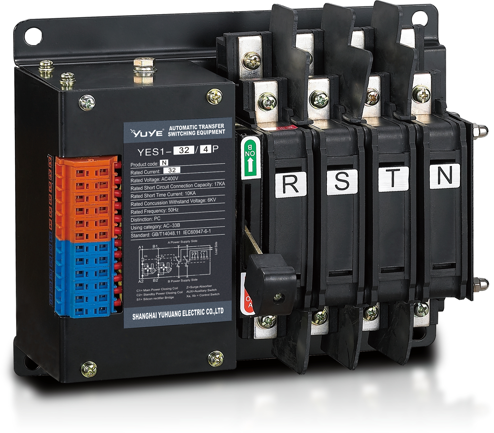 Solenoid-type ATS YES1-32~125N
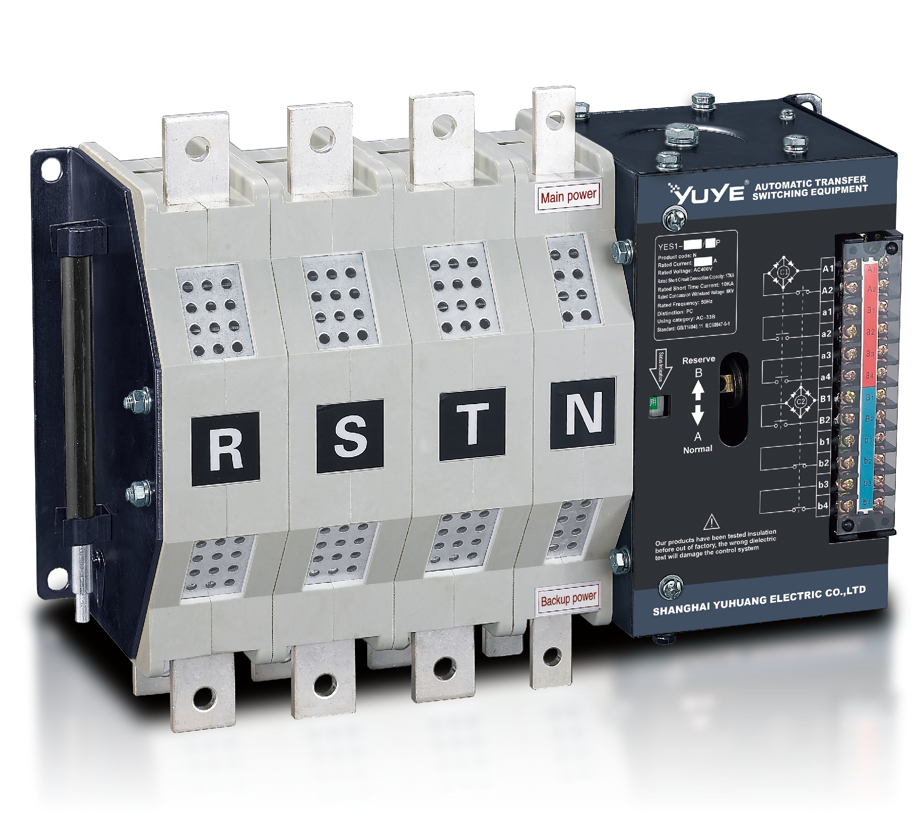 Solenoid-type ATS YES1-250~630N/NT
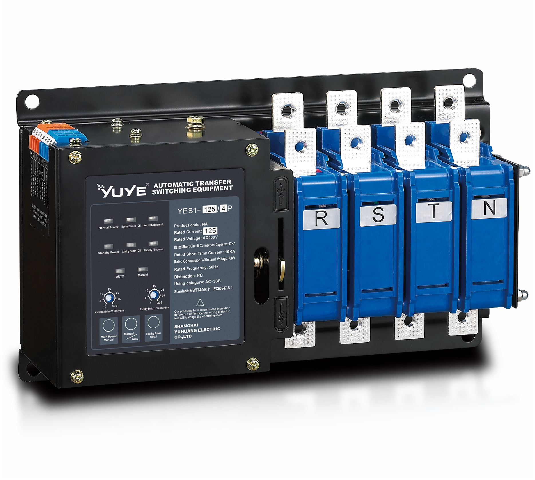 Solenoid-type ATS YES1-32~125NA
 Solenoid-type ATS YES1-63~630SN
 Solenoid-type ATS YES1-1250~4000SN
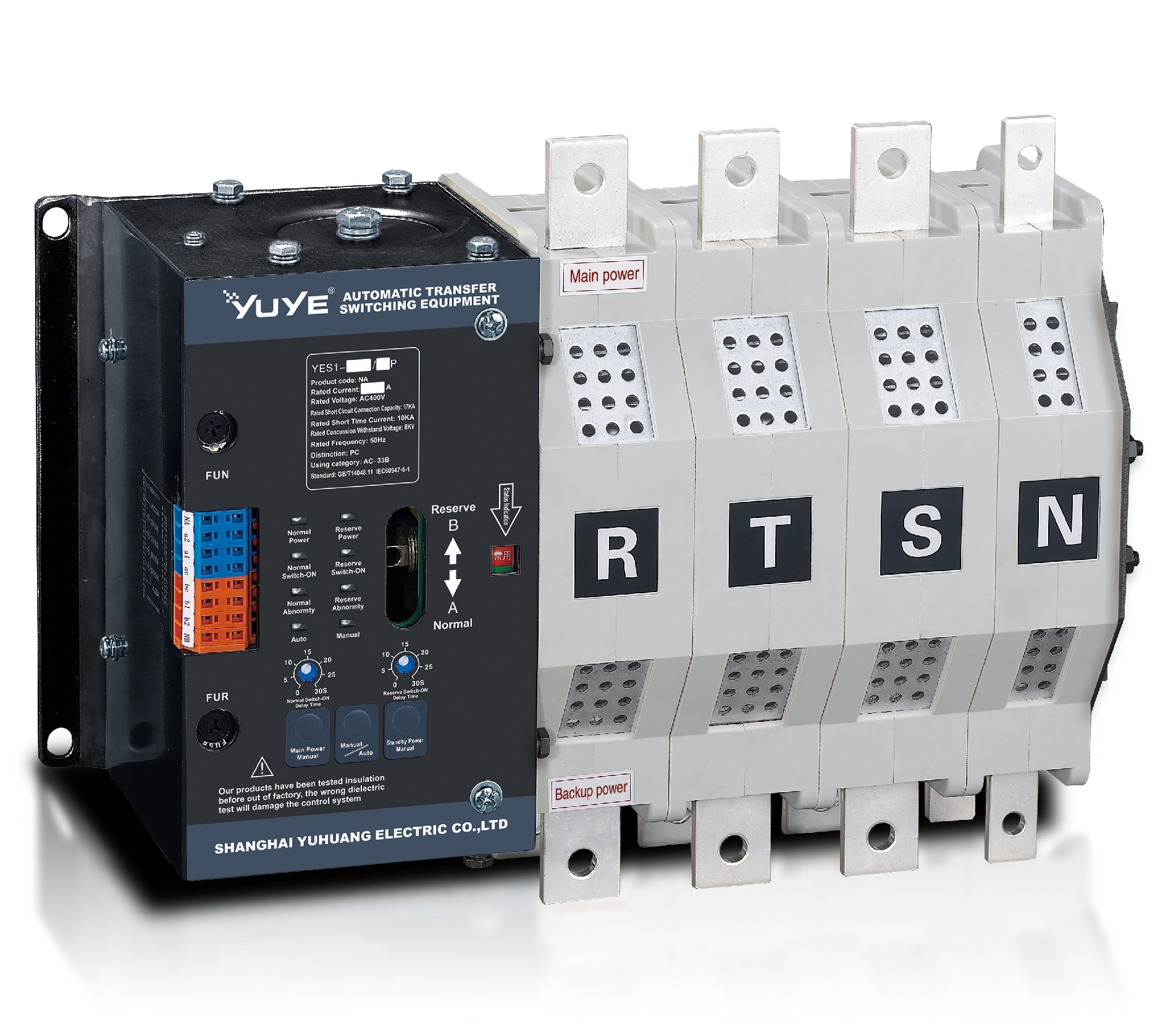 Solenoid-type ATS YES1-250~630NA/NAT
 Solenoid-type ATS YES1-63NJT
 PC ATS YES1-100~1600GN1/GN/GNF
 PC ATS YES1-2000~3200GN/GNF
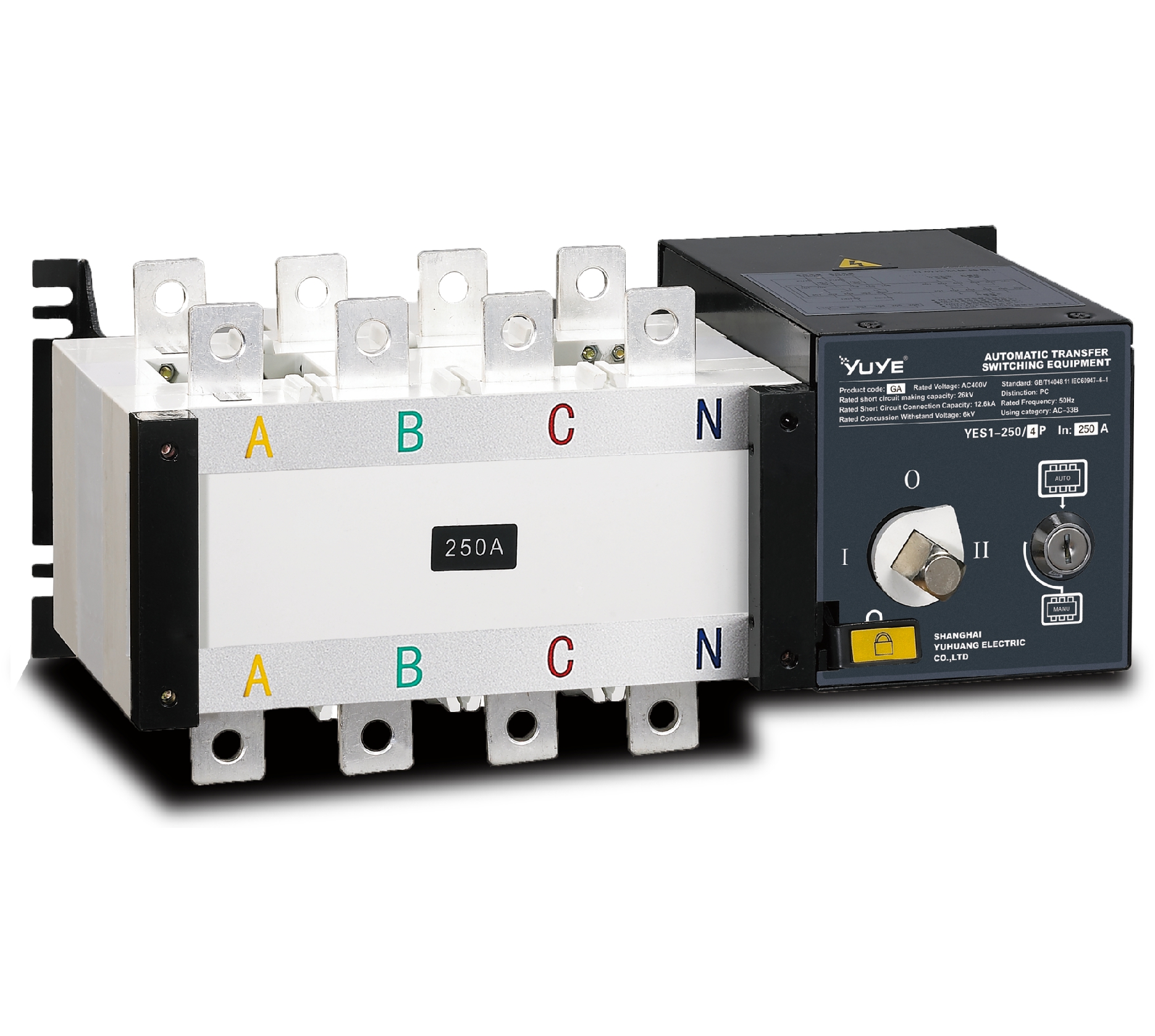 PC ATS YES1-100~3200GA1/GA
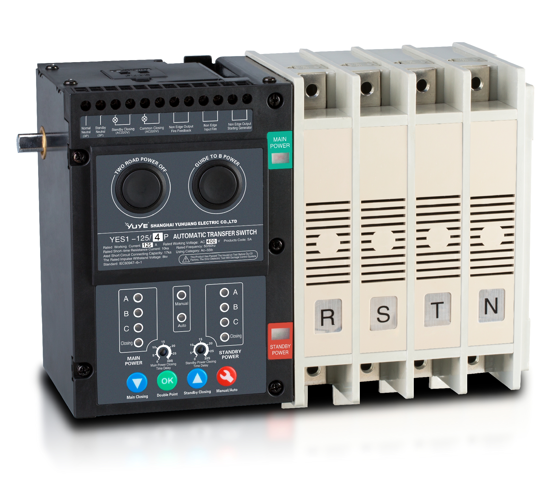 Solenoid-type ATS YES1-63~630SA
 Solenoid-type ATS YES1-63~630L/LA
 Solenoid-type ATS YES1-63~630LA3
 Solenoid-type ATS YES1-63MA
 PC ATS YES1-630~1600M
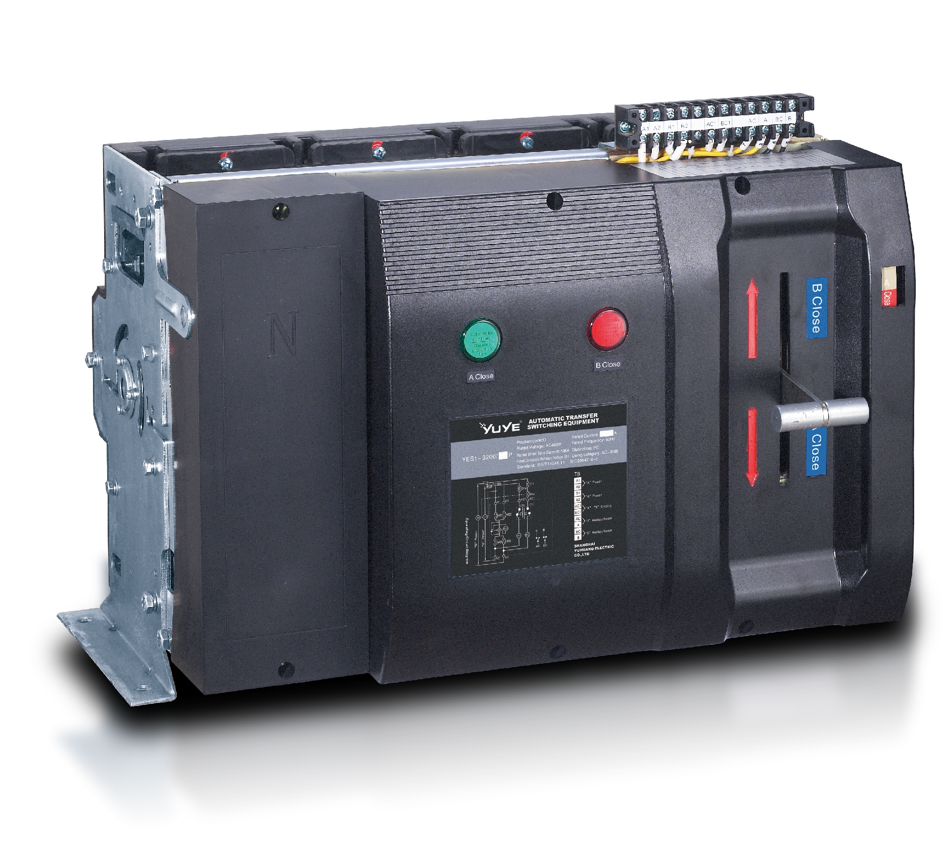 PC ATS YES1-3200Q
 Solenoid-type ATS YES1-4000~6300Q
 CB ATS YEQ1-63J
 CB ATS YEQ2Y-63
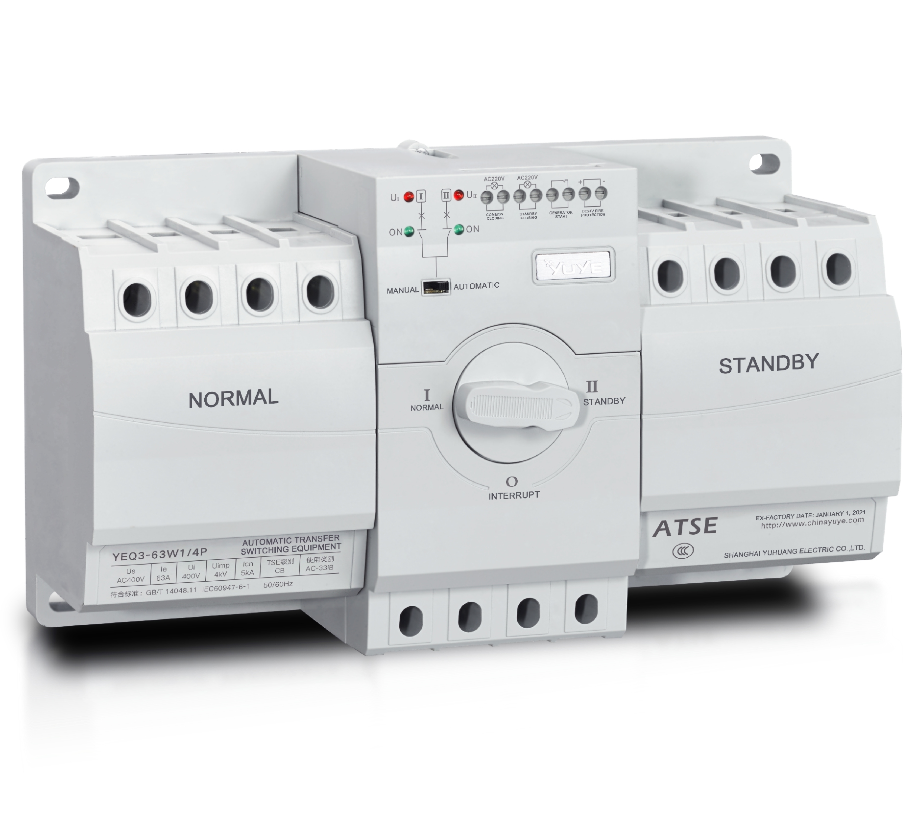 CB ATS YEQ3-63W1
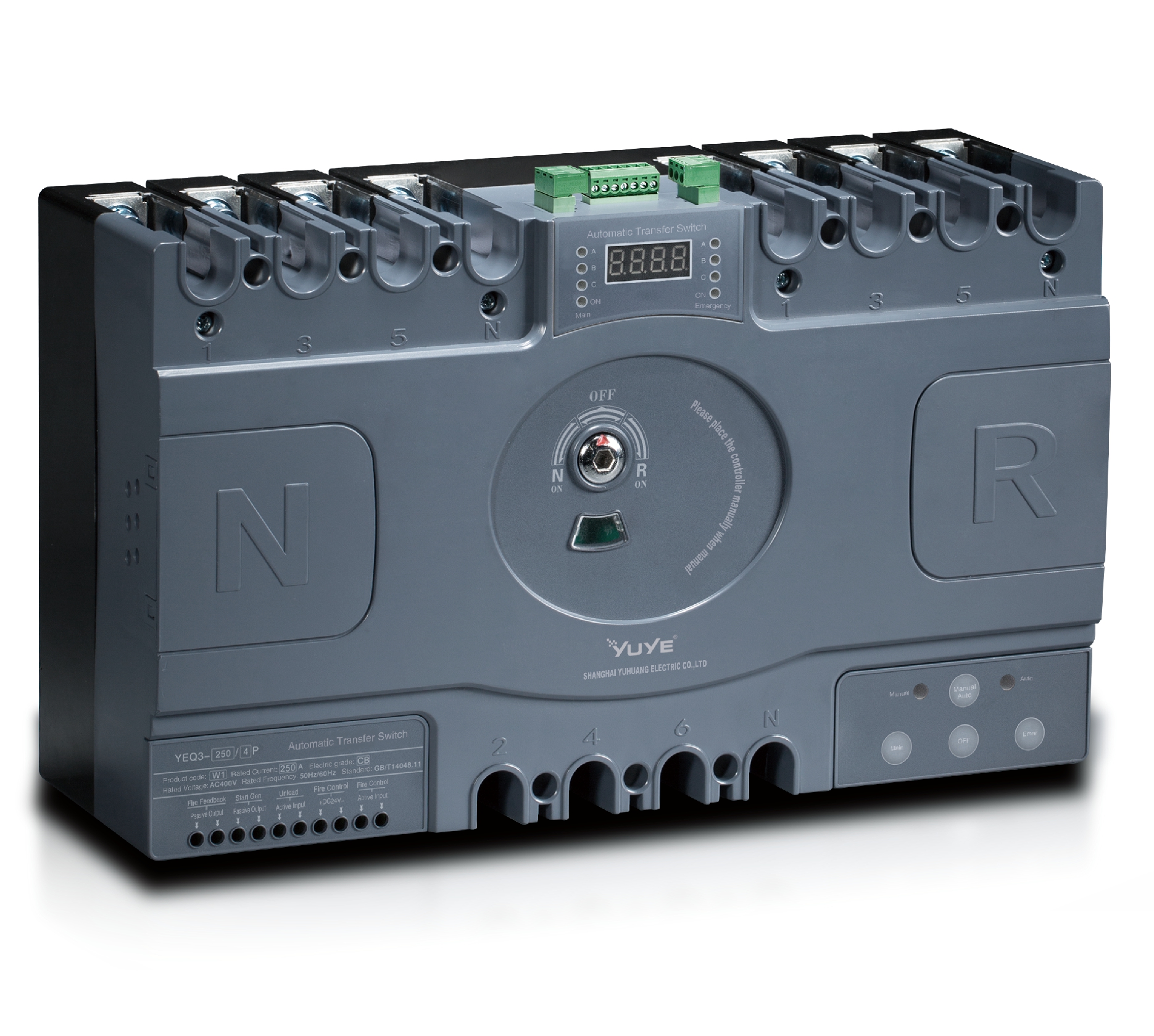 CB ATS YEQ3-125~630W1
 ATS controller Y-700
 ATS Controller Y-700N
 ATS Controller Y-701B
 ATS Controller Y-703N
 ATS Controller Y-800
 ATS Controller W2/W3 Series
 ATS switch Cabinet floor-to-ceiling
 ATS switch cabinet
 JXF-225A power Cbinet
 JXF-800A power Cbinet
 YEM3-125~800 Plastic Shell Type MCCB
 YEM3L-125~630 Leakage Type MCCB
 YEM3Z-125~800 Adjustable Type MCCB
 YEM1-63~1250 Plastic Shell Type MCCB
 YEM1E-100~800 Electronic Type MCCB
 YEM1L-100~630 Leakage Type MCCB
 Miniature circuit breaker YEMA2-6~100
 Miniature circuit breaker YEB1-3~63
 Miniature circuit breaker YEB1LE-3~63
 Miniature circuit breaker YEPN-3~32
 Miniature circuit breaker YEPNLE-3~32
 Miniature circuit breaker YENC-63~125
 Air Circuit Breaker YEW1-2000~6300
 Air Circuit Breaker YEW3-1600
 Load isolation switch YGL-63~3150
 Load Isolation Switch YGL2-63~3150
 Manual Changeover Switch YGL-100~630Z1A
 Manual Changeover Switch YGLZ1-100~3150
 YECPS2-45~125 LCD
 YECPS-45~125 Digital
 CNC Milling/Turning-OEM
 DC relay MDC-300M
 DC Isolation Switch YEGL3D-630
As a core device ensuring continuous power supply to critical loads, the reliable operation of an Automatic Transfer Switch (ATS) directly impacts the stability of the power system. However, during prolonged use, ATS units frequently experience technical failures due to internal component aging, external interference, or design flaws. These issues can cause abnormal switching functions or even power supply interruptions. The following outlines common technical faults in ATS units across four dimensions: switching performance, mechanical structure, electrical components, and control logic.
I. Switching Performance Failures: Direct Threats to Power Continuity
Switching functionality is the core of ATS operation. Failures here directly prevent normal switching between primary and backup power sources, representing the most common and dangerous technical issues. These primarily manifest as two categories: “Switching Failure” and “Mis-Switching.”
1. Switching Failure: Primary/Standby Power Fails to Switch as Required
• Causes:
Abnormal controller-sensor coordination is the primary cause. Examples include:
- Controller programming errors (e.g., failure to recognize primary power loss signals)
- Degraded sensor accuracy (voltage/frequency sensor detection errors exceeding thresholds)
- Power quality fluctuations (brief primary power dips causing controllers to misjudge “normal” status, or distorted standby voltage waveforms interfering with switching triggers) Additionally, mechanical actuator jamming (e.g., fused contactor contacts, rusted linkage mechanisms) can prevent completion of the switching action.
· Manifestation:
When the main power fails, the ATS fails to switch to the backup power, resulting in load power loss; or after backup power is restored, the ATS fails to switch back to the main power, causing prolonged load operation on the backup power and eventual fuel depletion in the generator. In extreme cases, simultaneous connection of both main and backup power (“parallel operation”) can trigger a power short circuit.
·Impact:
Data center server outages cause data loss; ICU equipment power failures threaten patient lives; industrial production line shutdowns result in economic losses.
2. Mis-switching: Unnecessary switching during normal operation
· Causes:
Incorrect controller parameter settings (e.g., voltage threshold set too low, triggering switching during normal main power fluctuations); external electromagnetic interference (harmonic interference from nearby inverters or welders disrupting sensor signals); loose wiring (poor contact in current sensor connections causing false “overload” alerts and triggering switching).
· Manifestation:
Sudden switching to backup power during normal main supply operation, or switching back to main power before backup conditions are met, causing brief load interruptions.
· Impact:
For sensitive loads (e.g., precision instruments, PLC control systems), even millisecond-level flash interruptions may cause program malfunctions or hardware damage.
II. Mechanical Structural Failures: Physical Operation Impediments
ATS switching relies on the precise coordination of mechanical actuators (e.g., contactors, linkages, springs). Failures often stem from mechanical wear, insufficient lubrication, or foreign object intrusion, manifesting as “sticking operation” and “poor contact point connection.”
1. Mechanical Sticking: Switching action stalls or fails to complete
· Causes:
Long-term lack of maintenance leading to lubrication failure (dry connecting rod pins, reduced spring elasticity), foreign object intrusion (dust/insects blocking movement paths), or component deformation from transport/installation impacts (bent linkages, misaligned housings).
· Symptoms:
Abnormal noises (metal friction sounds) during switching, prolonged switching time (far exceeding rated values), or partial contact failure (one or two phases not energized in a three-phase system).
· Impact:
Incomplete contact closure increases contact resistance, intensifies localized heating, and may cause contact welding during prolonged operation, ultimately burning out the ATS.
2. Poor Contact: The “Invisible Break” in the Conductive Path
·Causes:
Contact surface oxidation (prolonged non-switching exposes contacts to air, forming an oxide layer), arc erosion (frequent switching generates arcs that roughen contact surfaces), insufficient contact pressure (spring aging reduces closing force).
·Manifestation:
Abnormally elevated contact temperatures under load (infrared thermography shows readings exceeding 80°C), reduced load-end voltage (three-phase voltage imbalance), and severe cases triggering overcurrent protection.
·Impact:
Poor contact causing “loose connections” generates significant heat, accelerating aging of contacts and surrounding insulation materials, potentially leading to fires. Simultaneously, voltage fluctuations disrupt normal load operation (e.g., unstable motor speed, flickering lighting).
III. Electrical Component Failures: Control and Conductive System Malfunctions
Electrical components within ATS (e.g., controllers, contactor coils, fuses, transformers) are critical for executing the “sense-decide-act” cycle. Failures often stem from aging, overload, or design flaws.
1. Controller Malfunctions: “Brain” Function Abnormalities
· Causes:
Internal chip aging (semiconductor component degradation due to prolonged high-temperature environments), program loss (backup battery depletion causing parameter configuration data loss), damaged interface circuits (remote communication modules struck by lightning or surge impacts).
·Manifestations:
No display (black screen), unresponsive buttons, inability to communicate with the host computer, or erroneous fault codes (e.g., “backup power overvoltage” when actual voltage is normal).
·Impact:
Controller failure renders the ATS incapable of automatic switching, reducing it to a “manual switch” requiring human intervention and increasing the risk of power supply interruption.
2. Contactor Coil Burnout: Failure of the Actuator’s “Power Source”
· Causes:
Incompatible coil voltage with power supply (e.g., AC220V coil connected to AC380V power), prolonged energized state (controller failure causing continuous coil energization beyond rated operating time), coil interturn short circuit (insulation varnish aging/damage causing copper wire contact).
· Symptoms:
Coil emits smoke and burning odor; contactor fails to engage (coil open circuit) or remains stuck after engagement (coil short circuit causing continuous energization).
· Impact:
Coil burnout directly prevents ATS switching. Emergency contactor replacement is required; otherwise, load must rely on manual switching, increasing operational risks.
3. Fuse Blowing: Passive Triggering of Overcurrent Protection
· Causes:
Incorrect selection (fuse rated current lower than ATS rated current), load short circuit (downstream circuit fault causing short-circuit current exceeding fuse breaking capacity), poor contact (excessive contact resistance between fuse and base causing overheating and blowing).
· Symptoms:
After fuse blowout, the ATS control circuit or main circuit loses power and ceases normal operation. If the control circuit fuse blows, the controller loses power and switching functionality fails.
• Impact:
While fuse blowouts represent a “protective action,” frequent occurrences may mask underlying overloads in downstream circuits or the ATS itself. Root cause investigation is essential; otherwise, repeated fuse replacements increase maintenance costs and power interruption frequency.
IV. Control Logic and Signal Failures: “Misguided” Decision-Making Systems
ATS switching relies on a closed-loop logic of “detection-judgment-execution.” Errors in signal acquisition or logical judgment lead to “decision errors,” commonly arising from sensor anomalies or interlock logic conflicts.
1. Sensor Detection Anomalies: Distorted Input Signals
· Causes:
Degraded accuracy of voltage/current sensors (e.g., core saturation in electromagnetic voltage transformers causing poor output signal linearity), wiring errors (open circuits in current transformer secondary sides generating high voltage that damages sensors), environmental interference (strong electromagnetic fields superimposing noise on sensor output signals).
· Manifestation:
Controller displays voltage/frequency values inconsistent with actual conditions (e.g., “undervoltage” indication despite normal mains power), or detection signals exhibit severe fluctuations (value jumps).
· Impact:
Faulty detection signals cause controllers to misjudge power supply status, triggering unnecessary switching or refusal to switch, thereby compromising power supply stability.
2. Interlock Logic Conflict: Abnormal Multi-Device Coordination
·ATS often interfaces with generators, UPS, and other equipment (e.g., ATS triggers generator start after mains voltage loss, switching after standby power stabilizes). Defective interlock logic design or parameter mismatches can cause coordination failures.
·Causes:
Mismatched timing between generator start signals and ATS switching signals (ATS switches before generator reaches rated speed); UPS and ATS switching time conflicts (ATS fails to complete switching before UPS discharge ends); Remote and local control signal conflicts (simultaneous switching commands from monitoring systems and local controllers).
· Manifestation:
Generator starts but ATS fails to switch (standby power available but not engaged), or generator overload occurs after switching (ATS switching under load causes inrush current exceeding generator capacity).
·Impact:
Interlock failure prevents timely backup power engagement, or mutual interference between devices triggers secondary faults (e.g., generator overload shutdown).
Summary
ATS technical failures involve coordination issues across mechanical, electrical, and control systems. Root causes include both inherent equipment aging/wear and external environmental interference, closely linked to maintenance management. Identifying these common failures forms the basis for developing preventive measures and enhancing ATS reliability. Subsequent steps should focus on strengthening management in areas like selection, installation, and maintenance to reduce failure rates and ensure continuous power supply to critical loads.
The reliable operation of an Automatic Transfer Switch (ATS) depends not only on the product’s inherent quality but also on the standardization of its installation and maintenance. In practice, over 60% of ATS failures stem from improper installation or inadequate maintenance—issues that often remain “hidden.” While not immediately causing faults, they accelerate equipment aging, shorten service life, and ultimately lead to failure during critical moments.