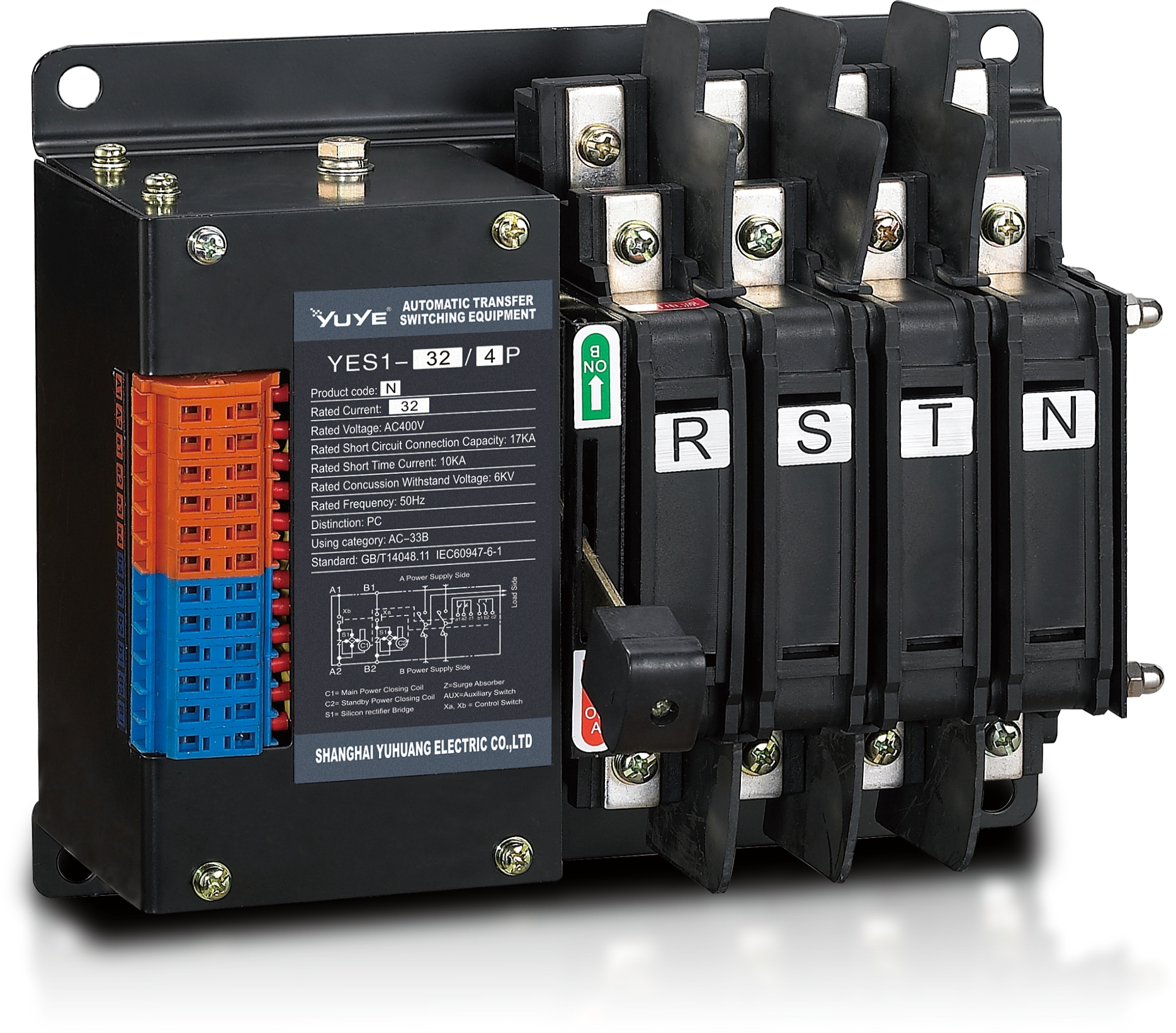
 PC Automatic transfer switch YES1-32N
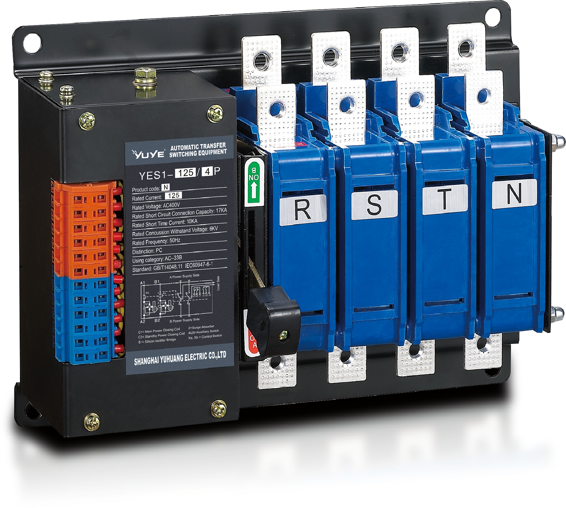 PC Automatic transfer switch YES1-125N
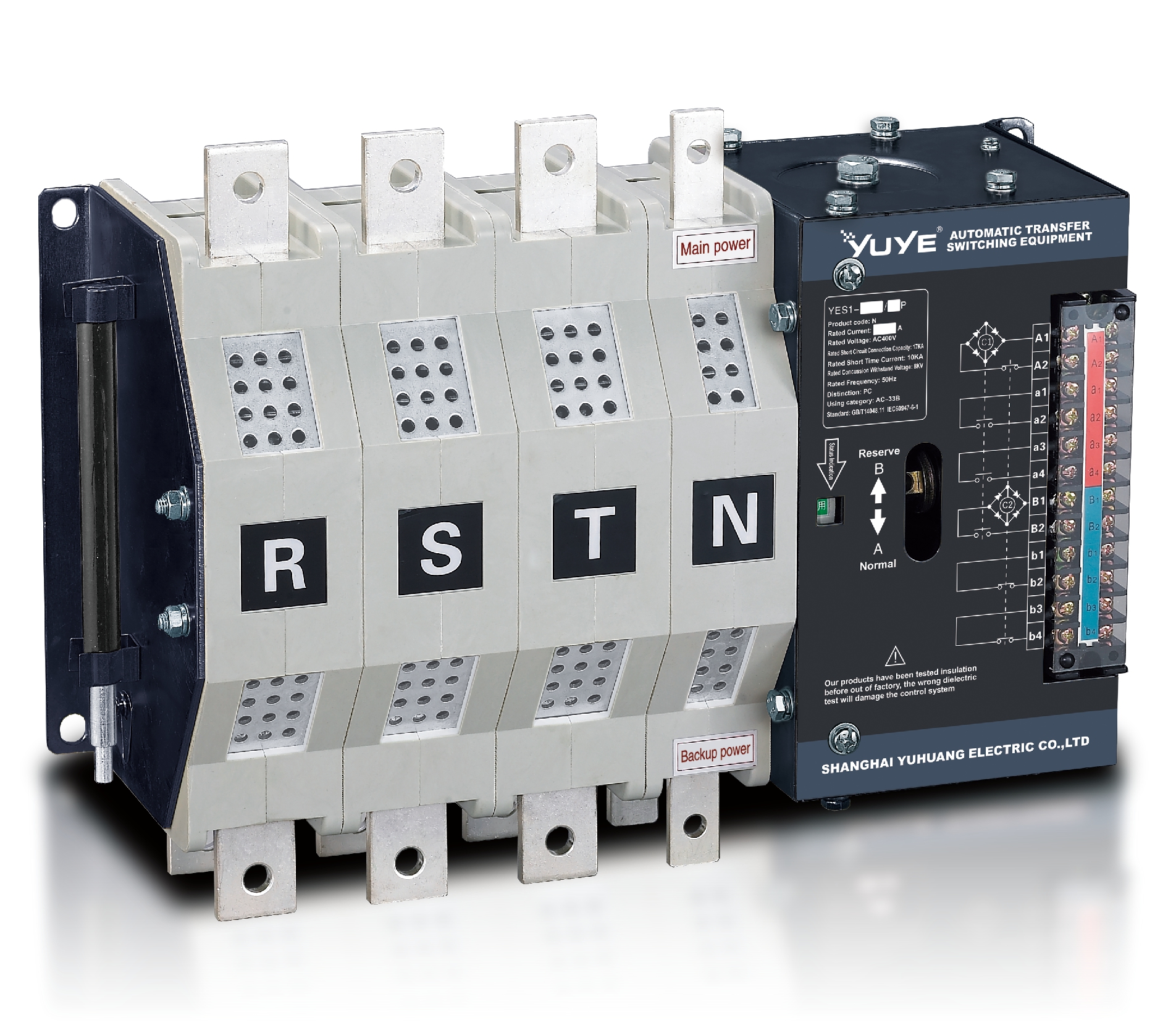 PC Automatic transfer switch YES1-400N
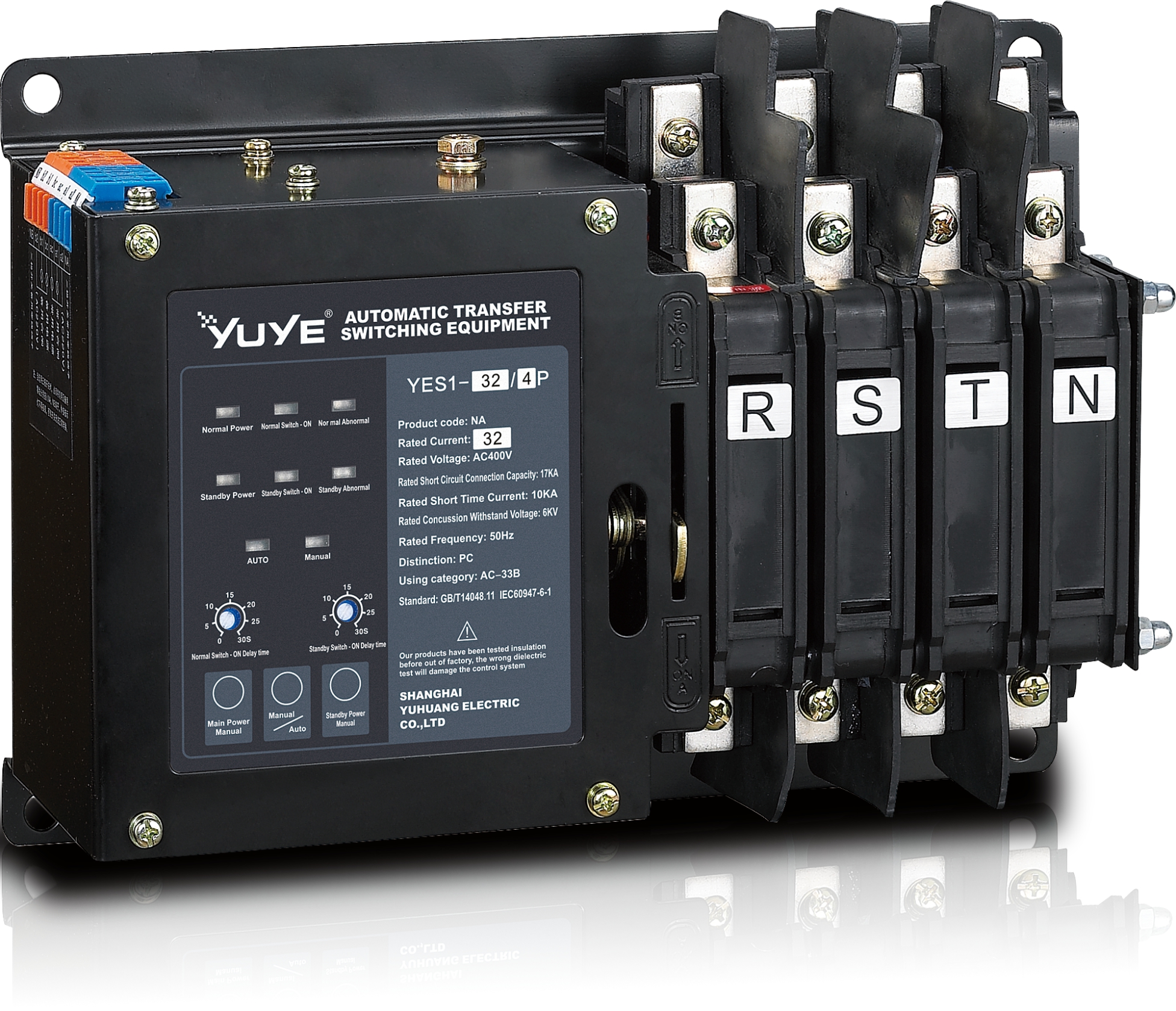 PC Automatic transfer switch YES1-32NA
 PC Automatic transfer switch YES1-125NA
 PC Automatic transfer switch YES1-400NA
 PC Automatic transfer switch YES1-100G
 PC Automatic transfer switch YES1-250G
 PC Automatic transfer switch YES1-630G
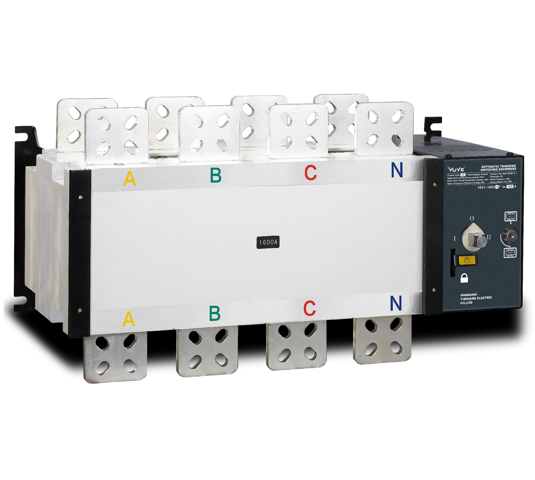 PC Automatic transfer switch YES1-1600G
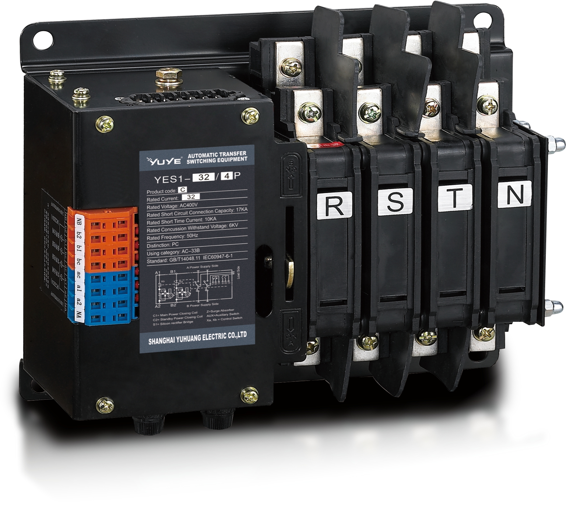 PC Automatic transfer switch YES1-32C
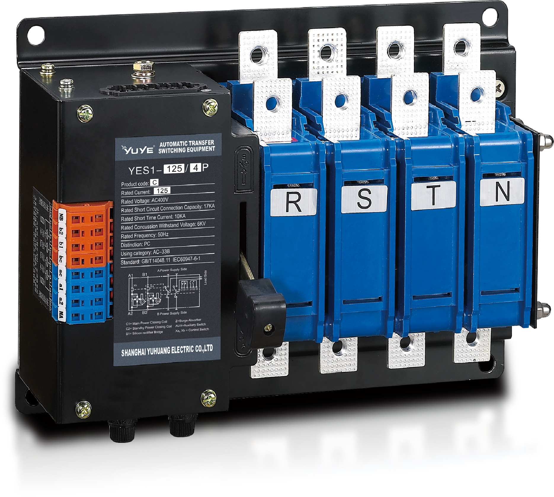 PC Automatic transfer switch YES1-125C
 PC Automatic transfer switch YES1-400C
 PC Automatic transfer switch YES1-125-SA
 PC Automatic transfer switch YES1-1600M
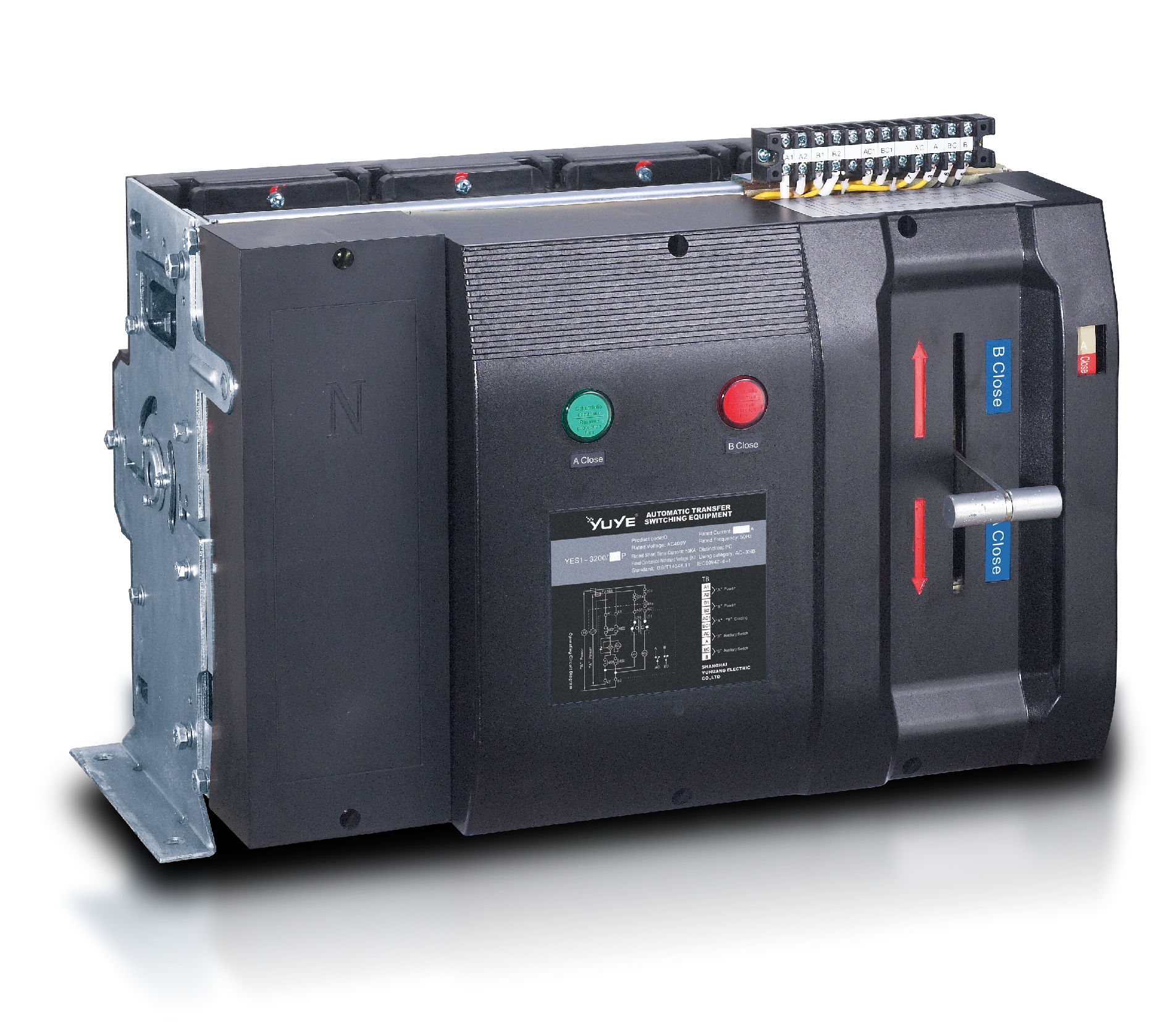 PC Automatic transfer switch YES1-3200Q
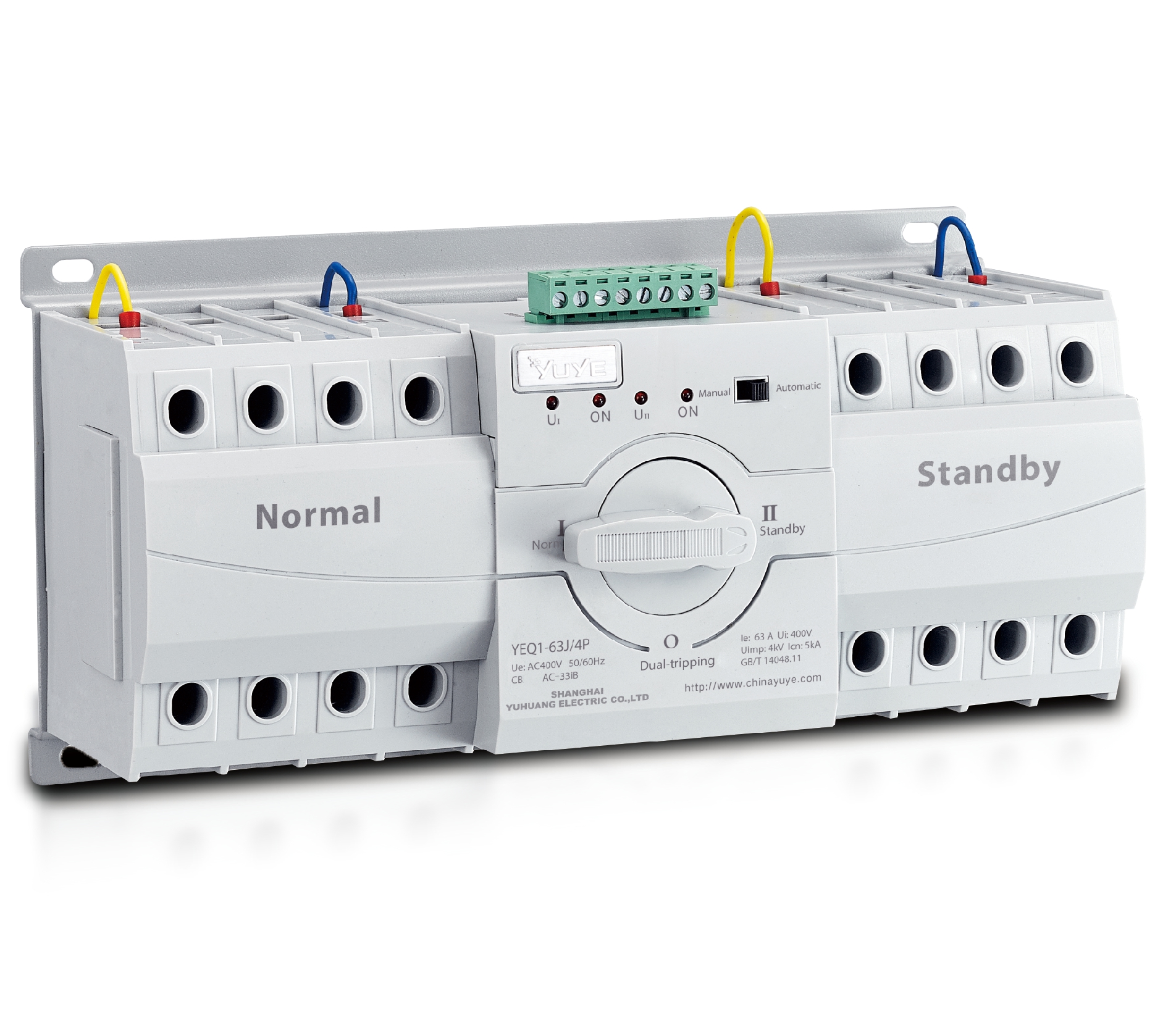 CB Automatic transfer switch YEQ1-63J
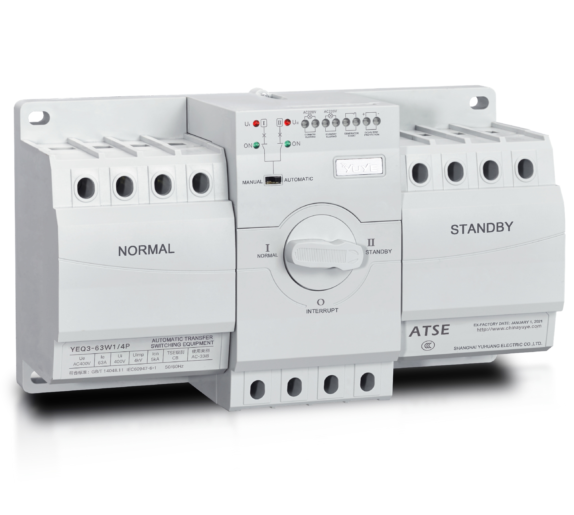 CB Automatic transfer switch YEQ3-63W1
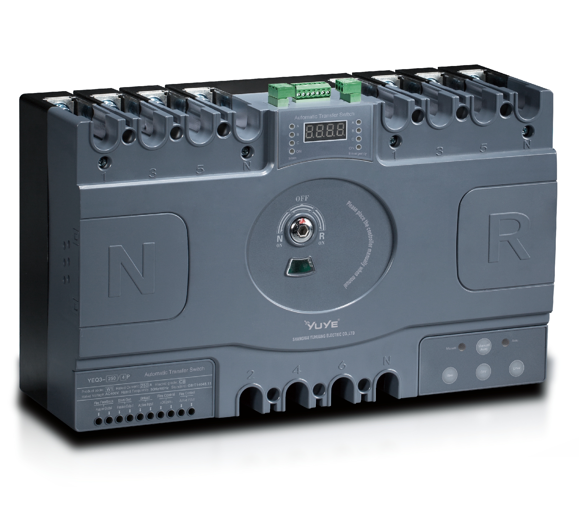 CB Automatic transfer switch YEQ3-125
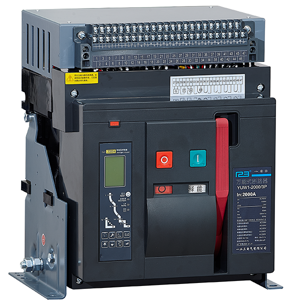 Air Circuit Breaker YUW1-2000/3P Fixed
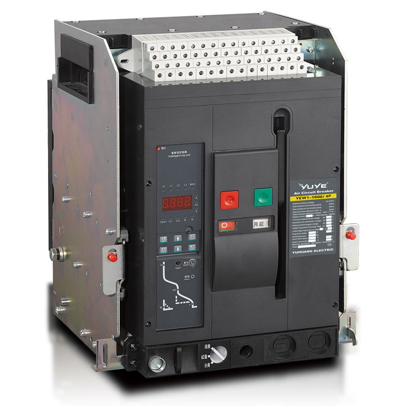 Air Circuit Breaker YUW1-2000/3P Drawer
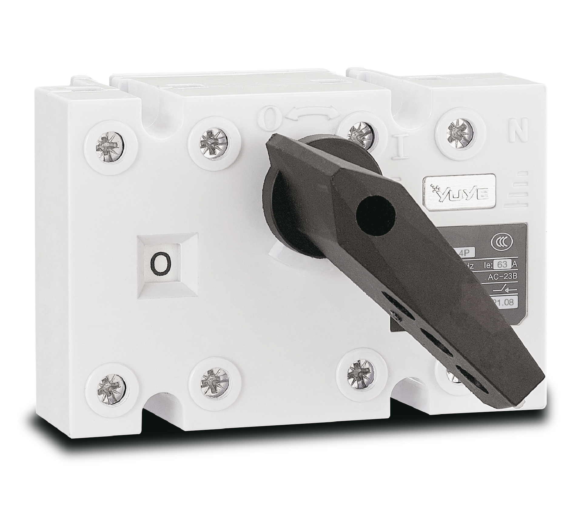 Load isolation switch YGL-63
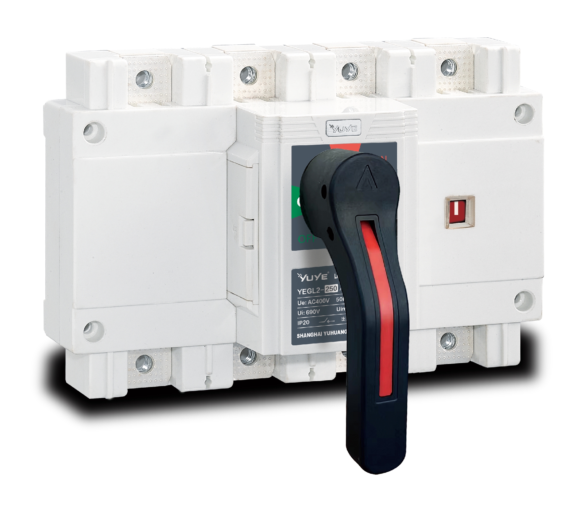 Load isolation switch YGL-250
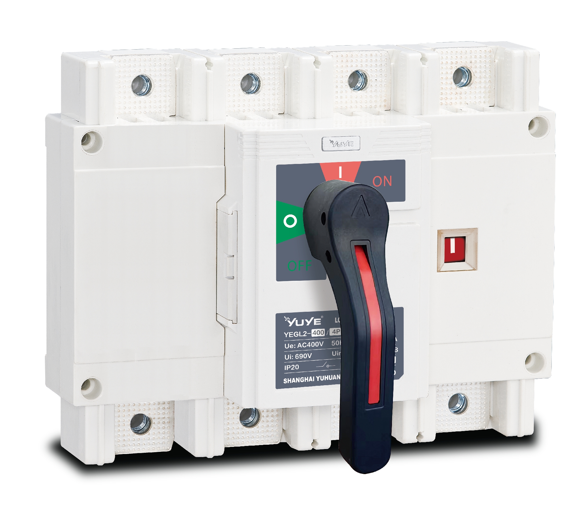 Load isolation switch YGL-400(630)
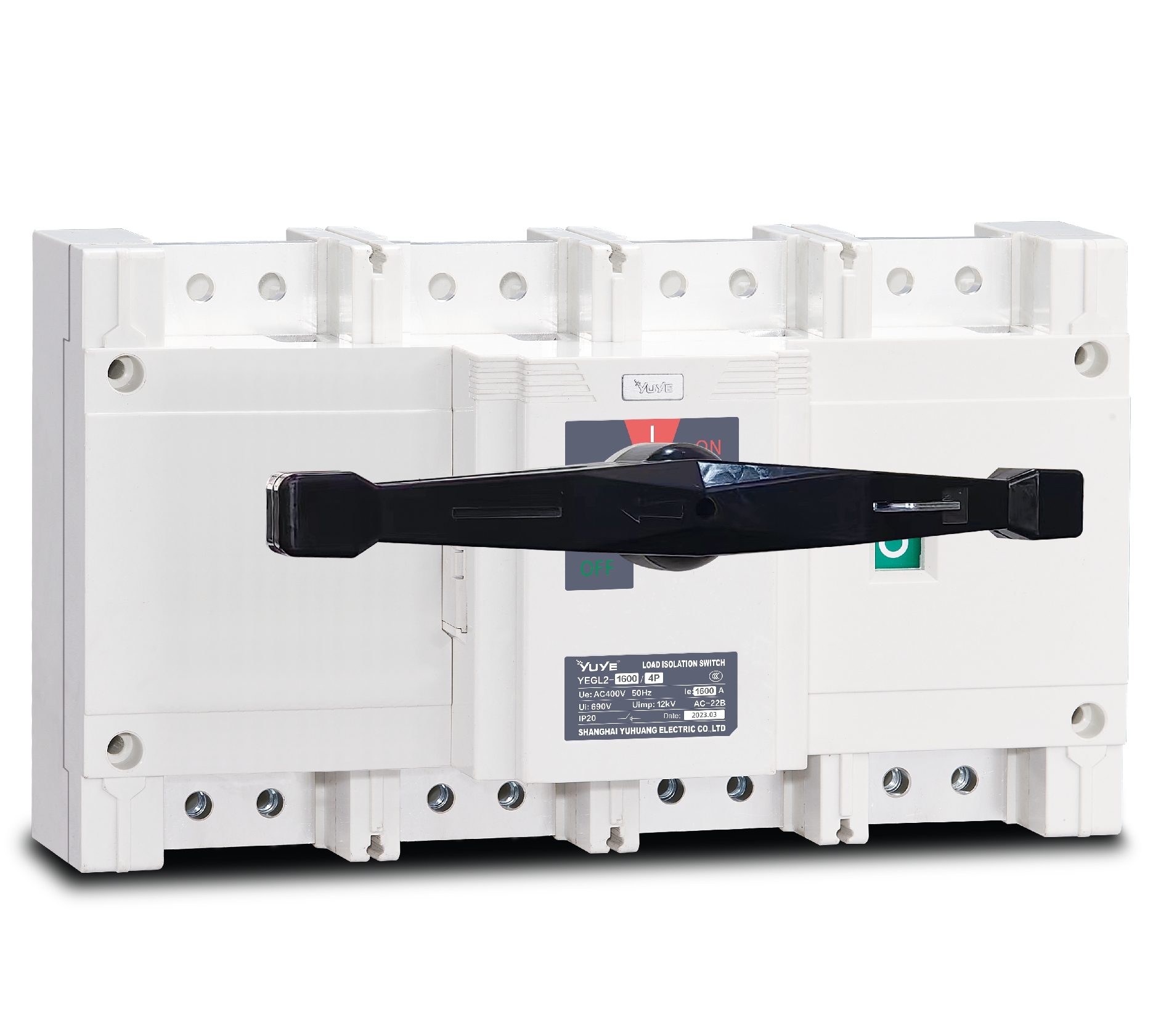 Load isolation switch YGL-1600
 Load isolation switch YGLZ-160
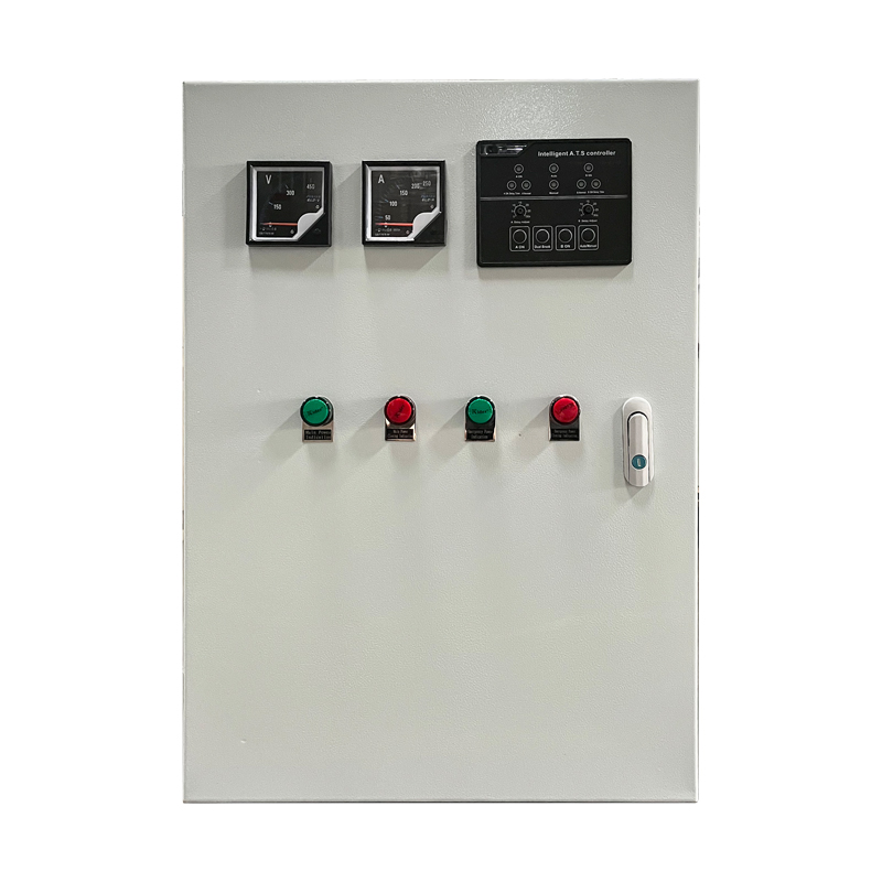 ATS switch Cabinet floor-to-ceiling
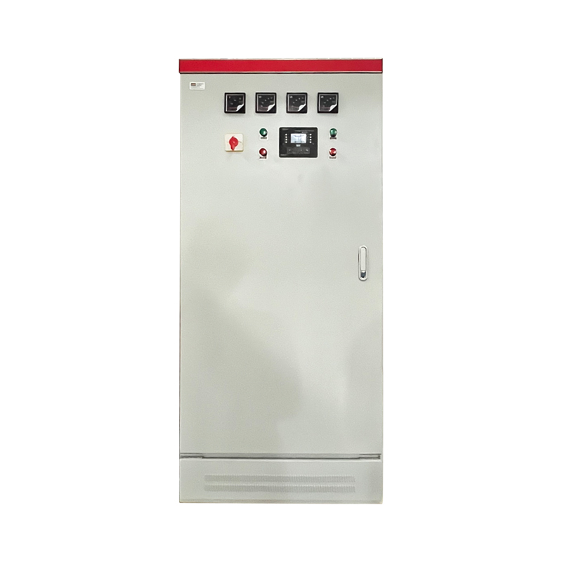 ATS switch cabinet
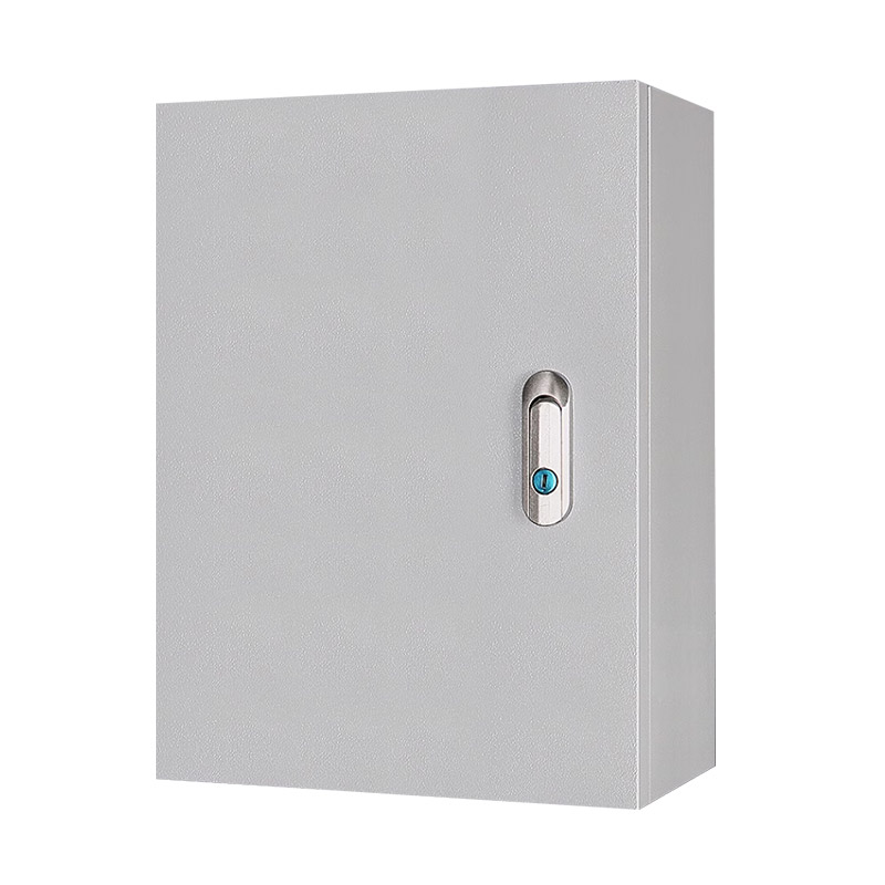 JXF-225A power Cbinet
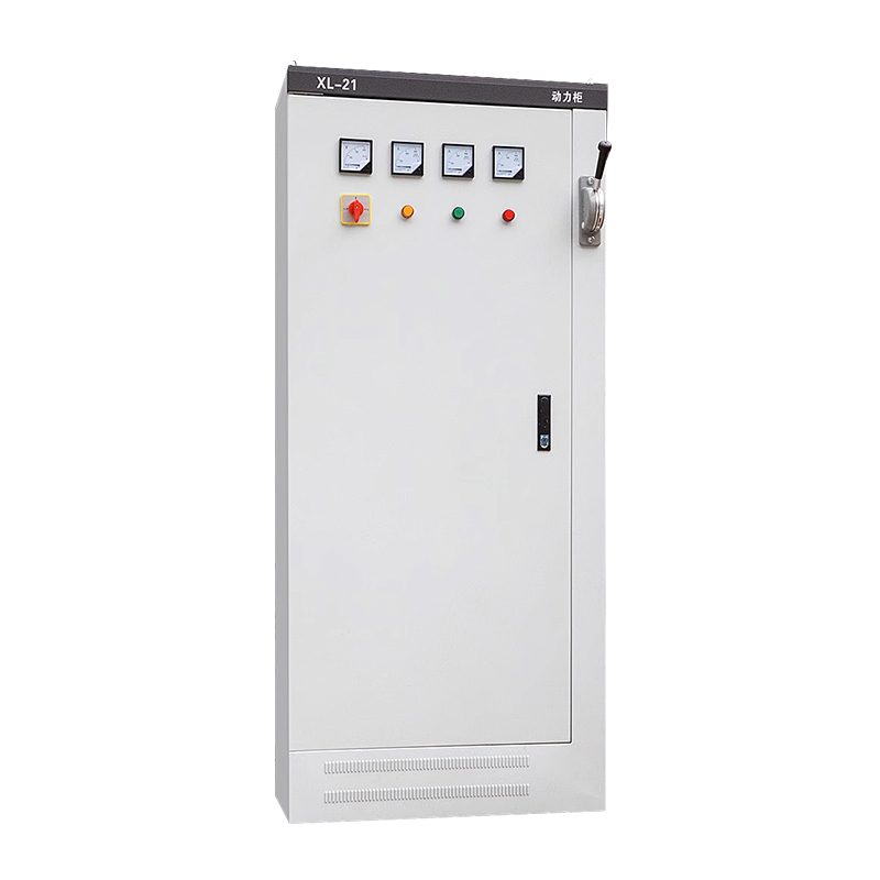 JXF-800A power Cbinet
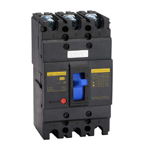 Molded case circuit breake YEM3-125/3P
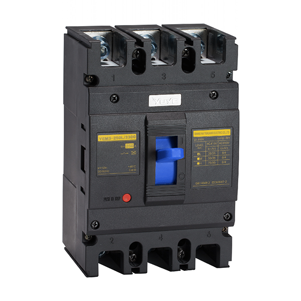 Molded case circuit breake YEM3-250/3P
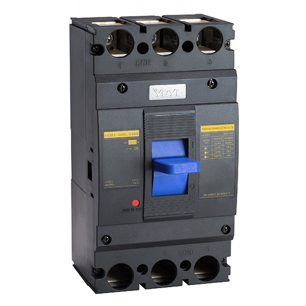 Molded case circuit breake YEM3-400/3P
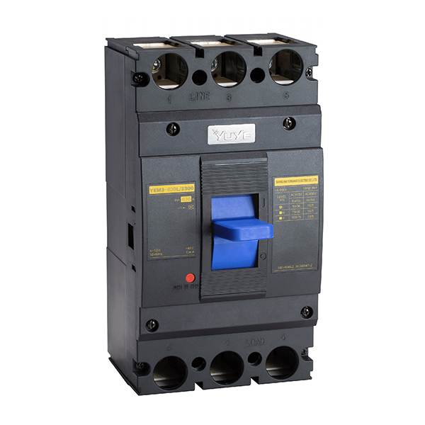 Molded case circuit breake YEM3-630/3P
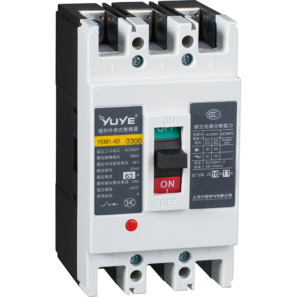 Molded case circuit breaker YEM1-63/3P
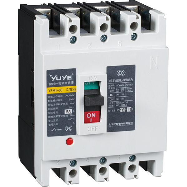 Molded case circuit breaker YEM1-63/4P
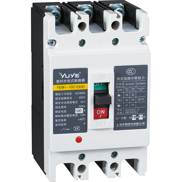 Molded case circuit breaker YEM1-100/3P
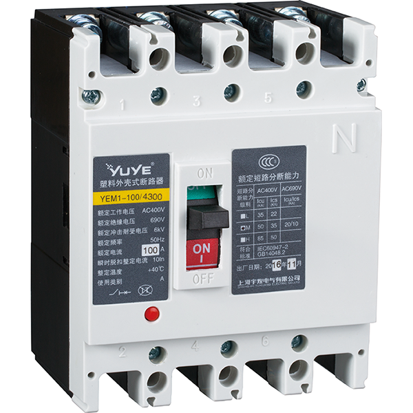 Molded case circuit breaker YEM1-100/4P
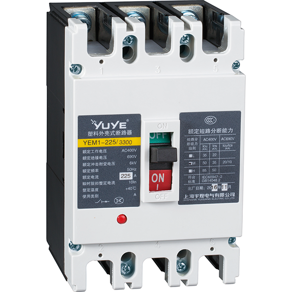 Molded case circuit breaker YEM1-225/3P
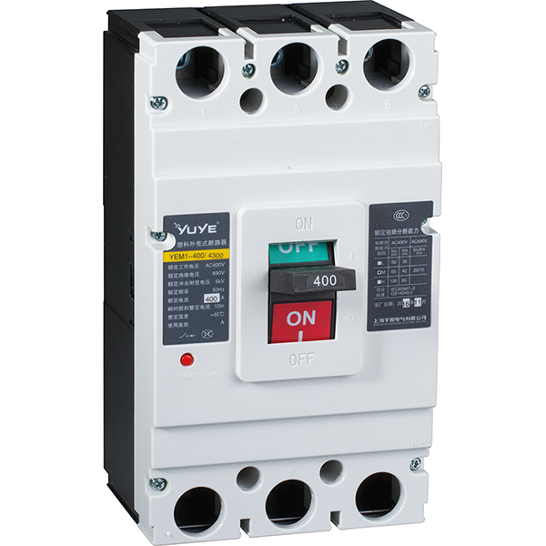 Molded case circuit breaker YEM1-400/3P
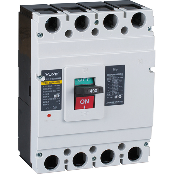 Molded case circuit breaker YEM1-400/4P
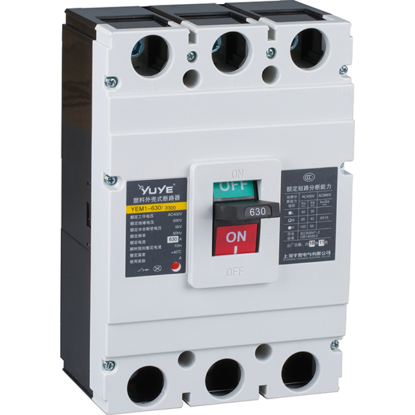 Molded case circuit breaker YEM1-630/3P
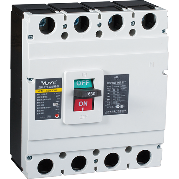 Molded case circuit breaker YEM1-630/4P
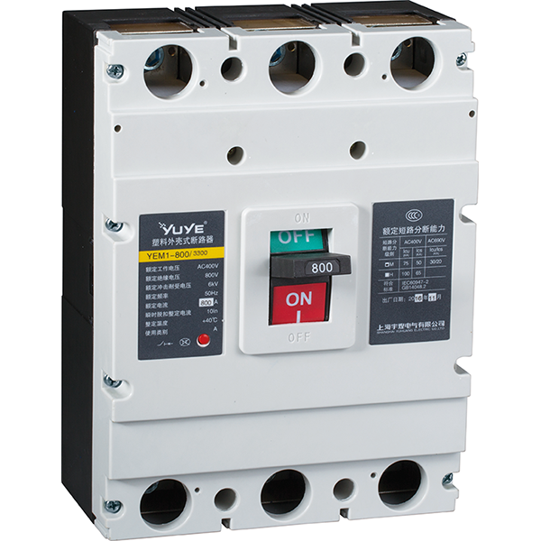 Molded case circuit breaker YEM1-800/3P
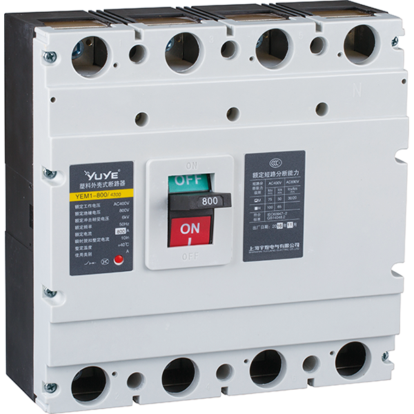 Molded case circuit breaker YEM1-800/4P
 Mold case circuit breaker YEM1E-100
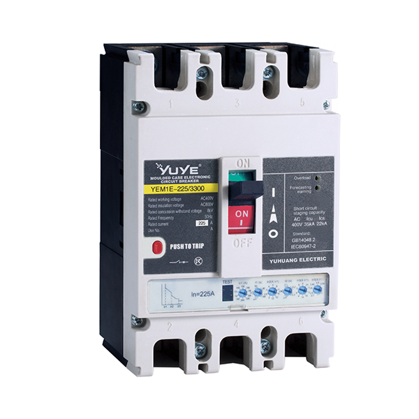 Molded case circuit breaker YEM1E-225
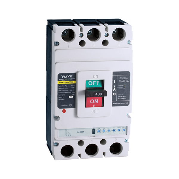 Molded case circuit breaker YEM1E-400
 Molded case circuit breaker YEM1E-630
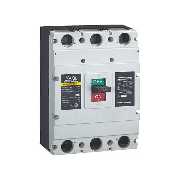 Mold case circuit breaker-YEM1E-800
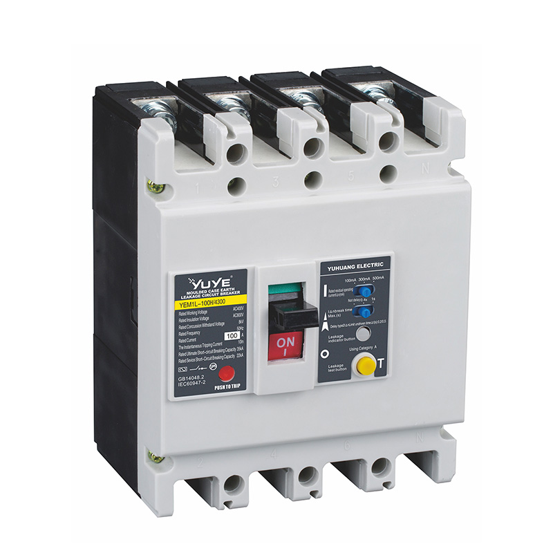 Molded case circuit breaker YEM1L-100
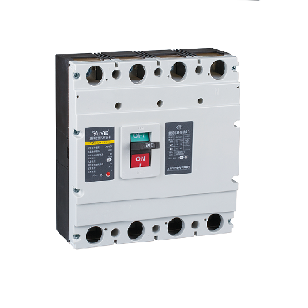 Molded case circuit breaker YEM1L-225
 Mold case circuit breaker YEM1L-400
 Molded case circuit breaker YEM1L-630
 Miniature circuit breaker YUB1-63/1P
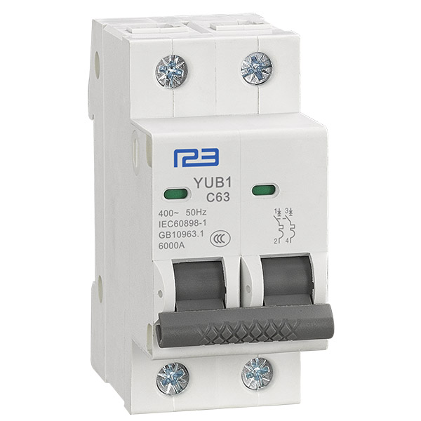 Miniature circuit breaker YUB1-63/2P
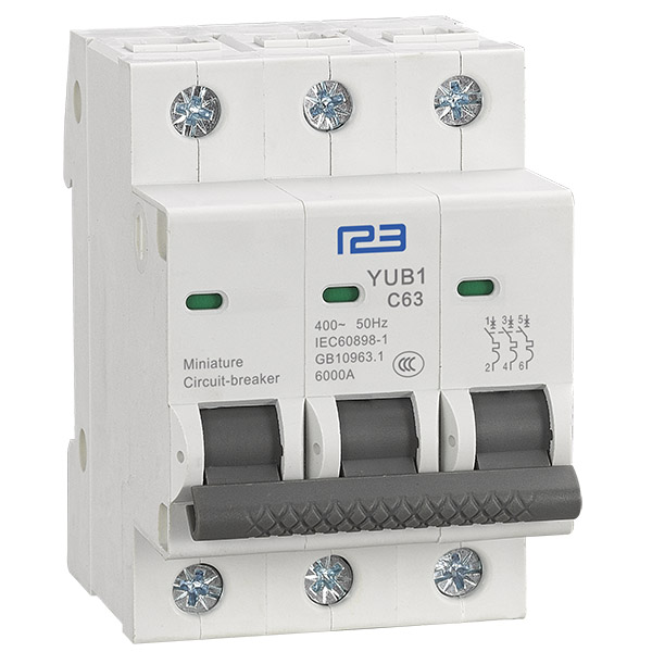 Miniature circuit breaker YUB1-63/3P
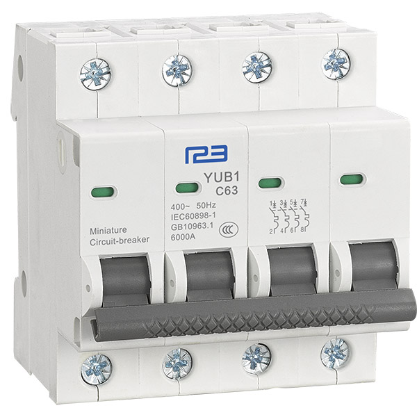 Miniature circuit breaker YUB1-63/4P
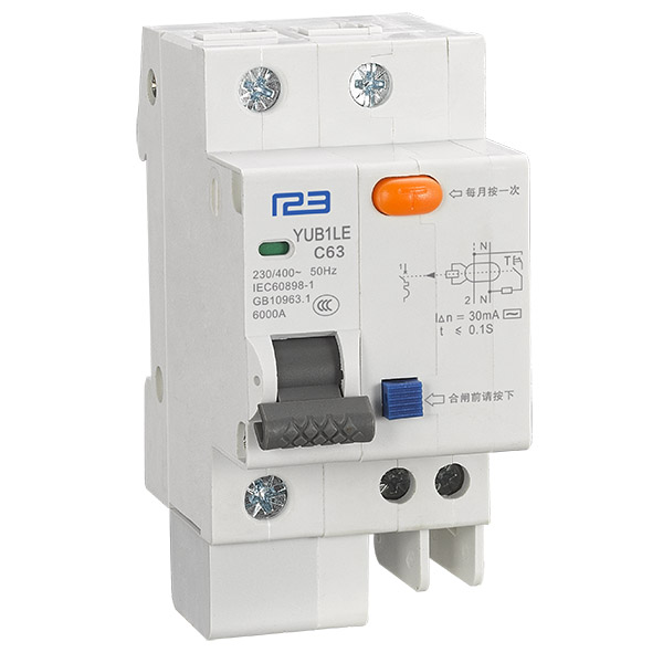 Miniature circuit breaker YUB1LE-63/1P
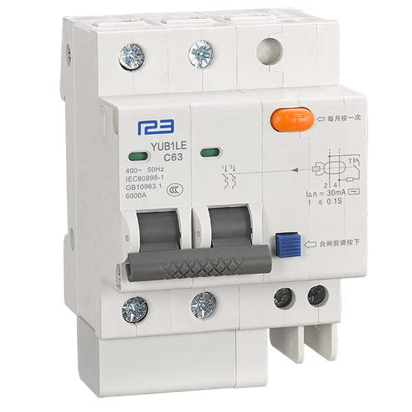 Miniature circuit breaker YUB1LE-63/2P
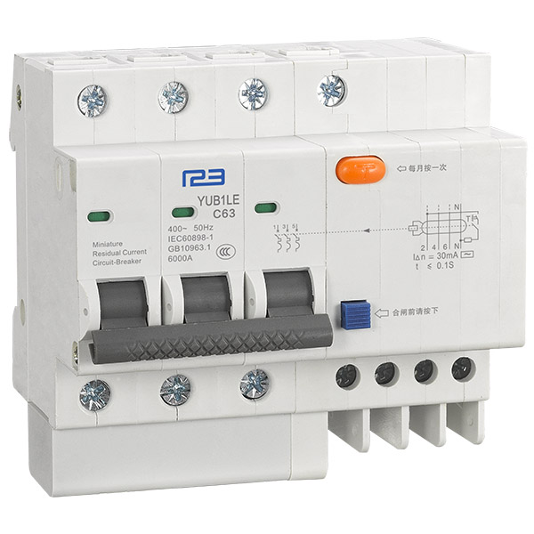 Miniature circuit breaker YUB1LE-63/3P
 Miniature circuit breaker YUB1LE-63/4P
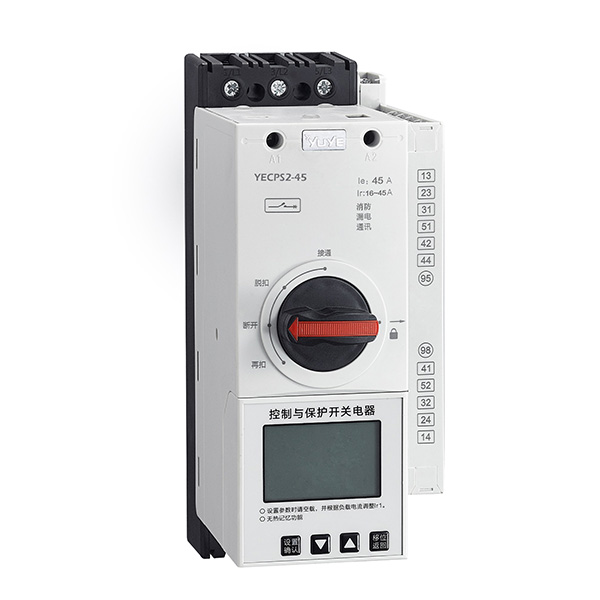 YECPS-45 LCD
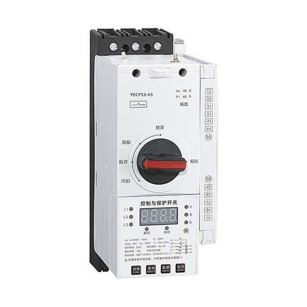 YECPS-45 Digital
 DC Automatic transfer switch YES1-63NZ
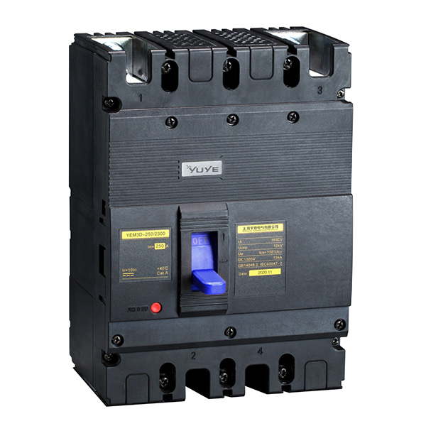 DC Plastic shell type circuit breaker YEM3D
 PC/CB Grade ATS Controller
Automatic transfer switch(ATSE) can solve the overlapping problem of neutral lines. So what do we mean by neutral line overlap?
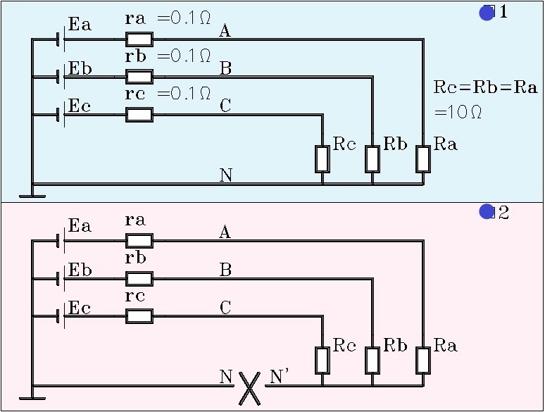
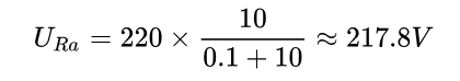
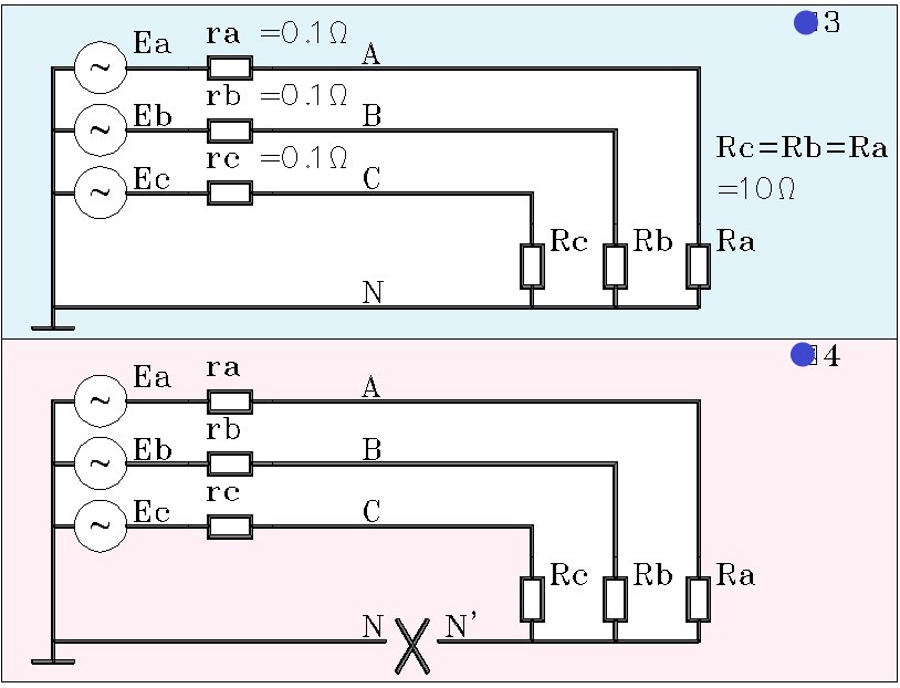
Figure 1: Assume that the voltage of the DC power supply is 220V, and the resistance value of the three load resistors R is 10 Ohms. Let’s calculate the voltage across the load resistor Ra:
For resistor Ra, we have:
Notice that there are three currents flowing through resistance Ra, one of which comes out of power supply Ea and returns to the negative pole of power supply through LINE N. The other two exit from Ea and return to the negative terminal via Eb or Ec. But because the electromotive forces of the two sources in this loop are equal and opposite, the current is zero.
Another thing that needs special attention is that the voltage at the N point is 0V.
Let’s look at figure 2 again: the N in the figure breaks into two points, N and N’. What is the voltage across the resistor Ra? It’s easy to tell that the voltage across Ra is 0V.
Of course, the premise here is: the three power supply parameters in the circuit are completely consistent, and the resistance parameters are also completely consistent, and even the parameters of the wire, namely the line resistance, are also completely consistent.
In a real line, these parameters will not be exactly the same, so the Ra will have a very low voltage. Let’s call it the N’ voltage.
Let’s look at the picture below:
As we can see, the power supply in FIG. 3 and 4, FIG. 1 and FIG. 2 is changed from DC to three-phase AC, and the phase voltage is 220V, so the line voltage is naturally 380V, and the phase difference between the three phases is 120 degrees.
What is the voltage across the resistor Ra in Figure 3?
Since the purpose of this post is only to illustrate the problem, not to do quantitative calculation of the circuit. We won’t have to do the exact calculation.
But we can definitely know that, for FIG. 3, the voltage across the resistor Ra is also approximately equal to 217.8V and the interphase voltage is zero.
In FIG. 4, we see that the n-line breaks into N and N’, so what happens to the voltage at the point N’?
The answer is exactly the same for DC. If the circuit is completely symmetric, Un ‘equals 0V; If the circuit parameters are inconsistent, Un ‘does not equal 0V.
In a practical circuit, especially in a lighting circuit, three-phase AC is asymmetric, so current flows through the N line or PEN line (zero line). Once the N line or PEN line breaks, the voltage behind the break point rises. In extreme cases, it goes up to the phase voltage, which is 220V.
Let’s take a look at ATSE:
See below:
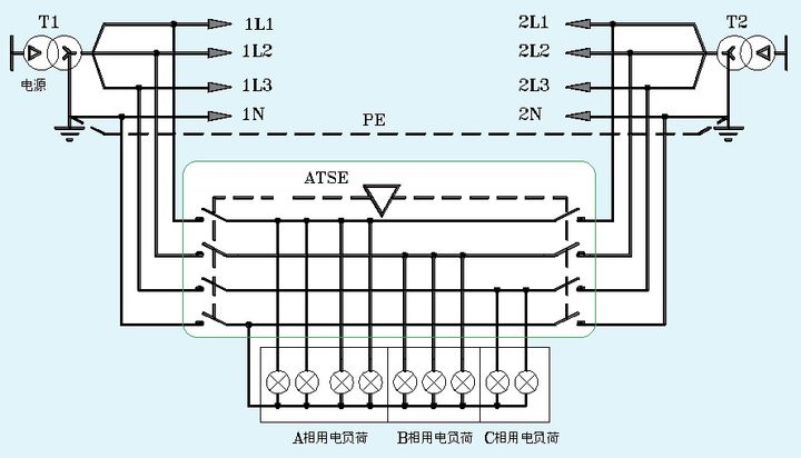
In this picture we see the dual incoming line, the ATSE, and of course the load light. Here, however, the number of lamps on the three phases varies, with phase A being the most heavily loaded.
Let’s imagine that ATSE now closes the T1 loop on the left, and the current operation is going from T1 to T2.
If, during the conversion, the 1N line is cut off first and the three phase is cut off later, then during the conversion, we can know immediately from the above knowledge that the neutral line voltage of the load may rise or fall. If the voltage on the lamp exceeds the phase voltage too much, the lamp will burn out during the conversion process.
That’s where the overlap of neutral lines comes in.
What’s the solution?
ATSE with neutral line overlapping function, when it is switched on, first ensure that the three-phase voltage is switched on first, and then N line is switched on at last; When it is turned on, first make sure to turn on the N line, and then turn on the three-phase voltage. Even, ATSE can overlap the N lines of both paths instantaneously. This is the neutral line overlap function.


